
Antenna coupling device

a technology of coupling device and antenna, which is applied in the direction of antenna earthing switch association, antenna support/mounting, electrical apparatus, etc., can solve the problems of inability to offer this facility in new models, inevitable losses, radiation inside the car,

Inactive Publication Date: 2003-08-26
SMARTEQ WIRELESS
View PDF3 Cites 61 Cited by
  • Summary
  • Abstract
  • Description
  • Claims
  • Application Information

AI Technical Summary

Benefits of technology

A main advantage with this antenna coupling device is that it is capable of operating in n independent frequency bands. This facilitates the work when designing an antenna coupling device.
Furthermore, it is an advantage in this context if each branch b.sub.ix has a constant width.
Furthermore, it is an advantage in this context if at least one of said branches b.sub.ix has a variable width along said branch b.sub.ix.
Furthermore, it is an advantage in this context if different branches b.sub.ix can intersect each other.

Problems solved by technology

However, the trend towards smaller, lighter and cheaper mobile telephones has led to new models which do not offer this facility.
If connection to a second antenna is desired, an electromagnetic coupler must be used, though this solution results in inevitable losses.
For the first, the couplers work in the near field of the first antenna impairing the drift of the telephone which may cause losses.
For the second, part of the electromagnetic energy cannot be picked up by the coupler, this results in radiation inside the car.
A complication is that operation at two frequency bands is required.
One disadvantage with this coupler is that the n frequency bands are not independent of each other, due to the fat that the coupler only has one branch.
This antenna coupler is intended to be tilted in relation to the antenna element in the mobile telephone with an angle, .alpha.. One disadvantage with this solution is that it implies a great distance between the coupler and the antenna element.
This fact reduces the coupling factor. another disadvantage is that this solution takes up too much space.

Method used


Image

  • Antenna coupling device
  • Antenna coupling device
  • Antenna coupling device

Examples


first embodiment

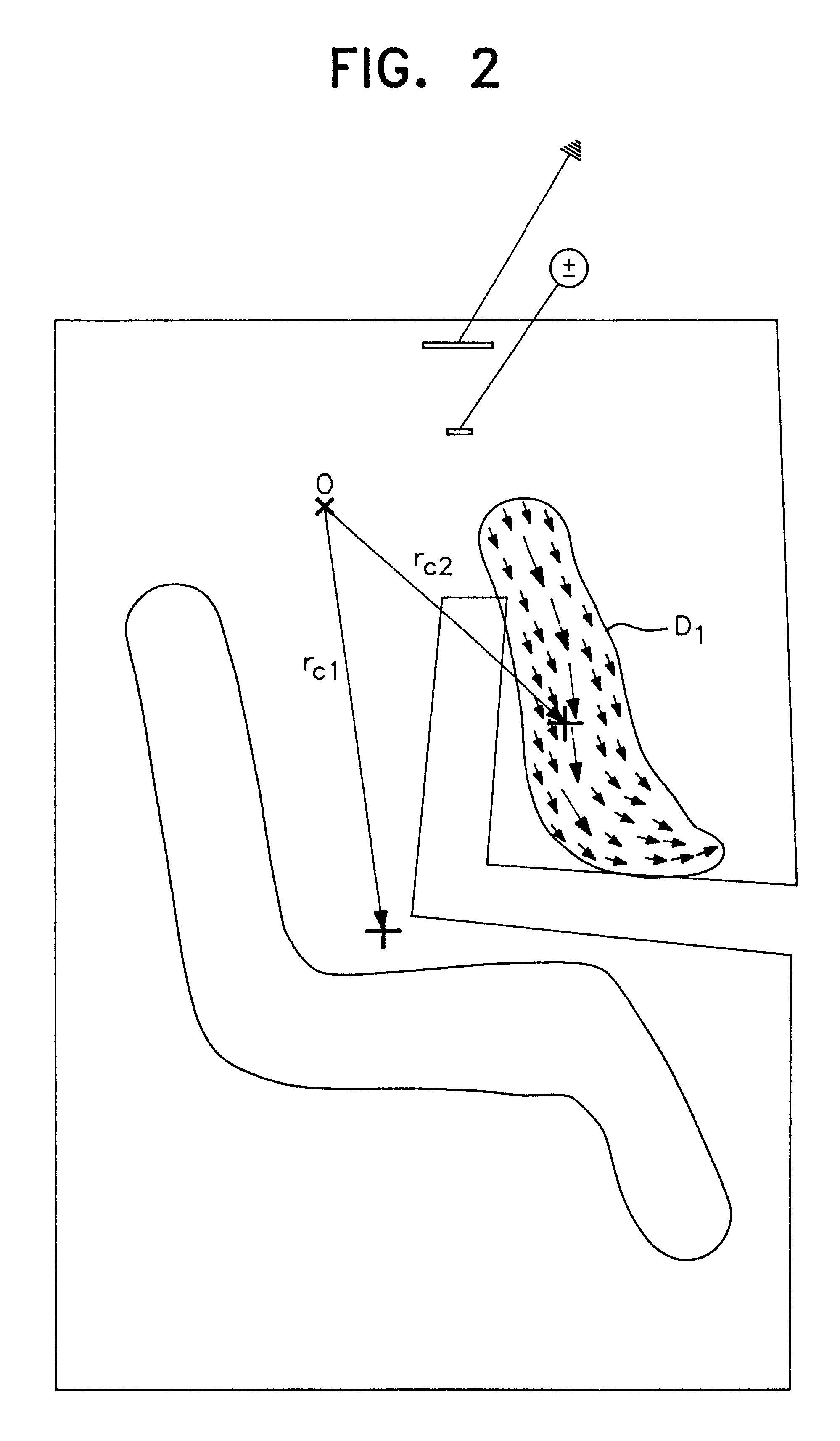
In FIGS. 2 and 3 there is disclosed the current density distribution for an internal first antenna, a so called dual band antenna, i.e. an antenna capable to operate at two different frequency bands 1 and 2. In FIG. 2 there is disclosed the current density distribution, illustrated with arrows, within the first domain, D.sub.1, for the frequency band 1. In FIG. 3 there is disclosed the current density distribution within the second domain, D.sub.2, for the second frequency band 2.

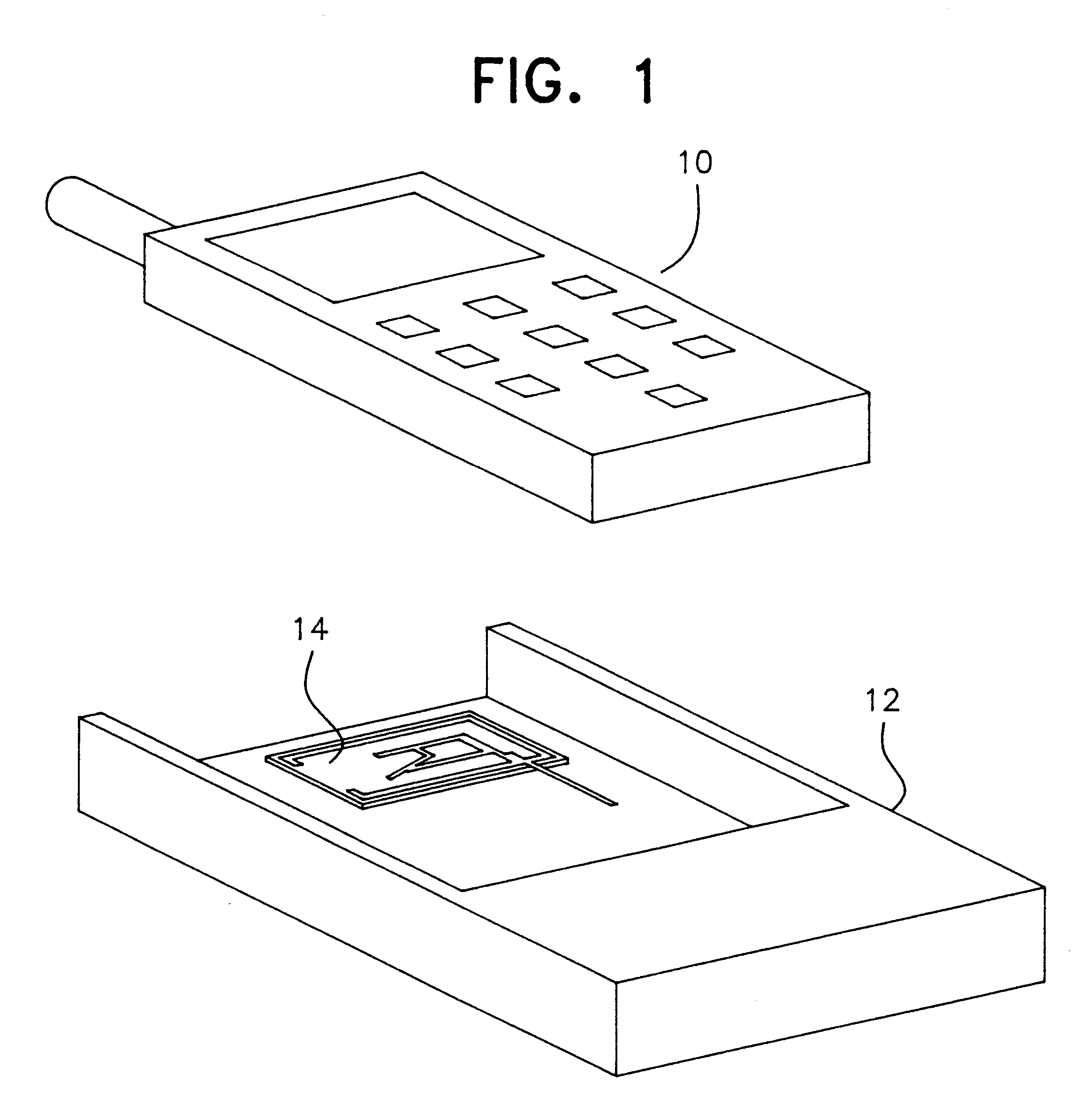
In FIGS. 4 and 5 there is disclosed a first embodiment of an antenna coupling device 14 according to the present invention, intended to be used with the first antenna according to FIGS. 2 and 3. The antenna coupling device 14 comprises a port 16 connected to a transmission line 18, here disclosed in the form of a coaxial cable 18. It is to be noted that the coaxial cable 18 is connected to the port 16 at two different points, i.e. the shield of the cable 18 is connected at one point and the centre conductor...

second embodiment

In FIGS. 6 and 7 there is disclosed the current density distribution for an internal first antenna, a so called dual band antenna, i.e. an antenna capable to operate in two different frequency bands 1 and 2. In FIG. 6 there is disclosed the current density distribution within the first domain, D.sub.1, for the frequency band 1. In FIG. 7 there is disclosed the current density distribution within the second domain, D.sub.2, for the second frequency band 2.

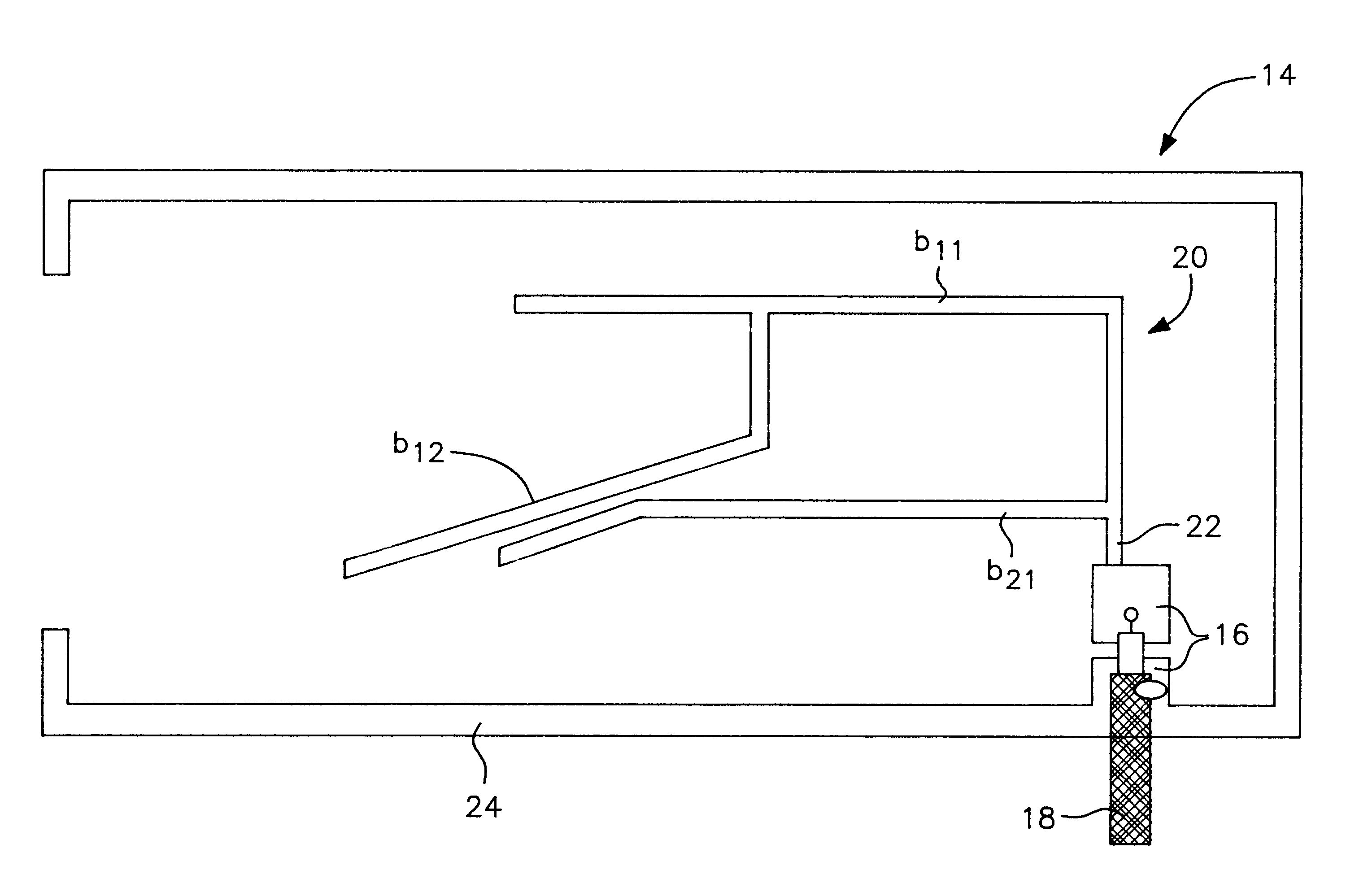
In FIGS. 8 and 9 there is disclosed a second embodiment of an antenna coupling device 14 according to the present invention, intended to be used with the first antenna according to FIGS. 6 and 7. The antenna coupling device 14 comprises a port 16 connected to a coaxial cable 18. The conducting surface of the antenna coupling device 14 has a geometric shape in the form of a tree structure 20 connected to said port 16. The tree structure 20 comprises a stem 22 which starts at said port 16 and tree branches b.sub.11, b.sub.12 and b.sub...

third embodiment

In FIGS. 10-12 there is disclosed the current density distribution for an internal first antenna, a so called triple band antenna, i.e. an antenna capable to operate in three different frequency bands 1, 2 and 3. In FIG. 10 there is disclosed the current density distribution within the firs domain, D.sub.1, for the frequency band 1. In FIG. 11 there is disclosed the current density distribution within the second domain, D.sub.2, for the frequency band 2. In FIG. 12 there is disclosed the current density distribution within the third domain, D.sub.3, for the frequency band 3.

In FIGS. 13 and 14 there is disclosed a third embodiment of an antenna coupling device 14 according to the present invention, intended to be used with the first antenna according to FIGS. 10-12. The antenna coupling device 14 comprises a port 16 connected to a coaxial cable 18. The conducting surface of the antenna coupling device 14 has a geometric shape in the form of a tree structure 20 connected to said port ...


PUM


Abstract

The present invention relates to an antenna coupling device (14) for coupling radio frequency signal from a communication device (10) having an internal first antenna, the communication device (10) operable in n frequency bands, where n>1 and n is an integer. The antenna coupling device (14) comprises a port (16) connected / connectable to a transmission line (18). A conducting surface of said antenna coupling device (14) has a geometric shape in the form of a tree structure (20) connected to said port (16). The tree structure (20) comprises a number, m, of branches, where m>=n, wherein said tree structure (20) comprises at least one branch bix for each frequency band I of said communication device (10), wherein I is an integer and 1<=I<=n, and x is an integer and 1<=x<=k (i), and the total number, m, of branches satisfy the following expressionwherein k (i) is a function of I, which only can obtain an integer value and is the total number of branches for frequency band.

Description

The present invention relates to an antenna coupling device for coupling radio frequency signals from a communication device having an internal first antenna.DESCRIPTION OF RELATED ARTSome older types of mobile telephones have been equipped with a coaxial connector to which a conductor to a second antenna can be attached, simultaneously disconnecting the first antenna of the telephone. However, the trend towards smaller, lighter and cheaper mobile telephones has led to new models which do not offer this facility. If connection to a second antenna is desired, an electromagnetic coupler must be used, though this solution results in inevitable losses. For the first, the couplers work in the near field of the first antenna impairing the drift of the telephone which may cause losses. For the second, part of the electromagnetic energy cannot be picked up by the coupler, this results in radiation inside the car.Different models of couplers are needed to fit different types of telephones de...

Claims


Application Information

Patent Timeline
Patent Type & Authority Patents(United States)
IPC IPC(8): H01Q1/24H01Q5/00H01Q9/04
CPCH01Q1/243H01Q5/371H01Q9/0407
Inventor BARNA, ZSOLTLINDBERG, PETER
Owner SMARTEQ WIRELESS
Learn More