Optical flow sensor using a fast correlation algorithm

a technology of optical flow sensor and correlation algorithm, which is applied in the field of optical flow sensor, can solve the problems of inaccurate flow rate measurement, inability to accurately estimate the flow rate achieved with such instruments, and inability to meet the needs of industrial and environmental applications

Inactive Publication Date: 2003-08-26
OPTICAL SCI
View PDF4 Cites 23 Cited by
  • Summary
  • Abstract
  • Description
  • Claims
  • Application Information

AI Technical Summary

Benefits of technology

From these calculations, the cross correlations C.sub.1, C.sub.2, C.sub.4 . . . C.sub.N / 2 can be obtained to retrieve the crosswind. The major advantage of the Fast Correlation Algorithm (FCA) is that the total number of calculations is proportional to 2N instead of N.sup.2. This represents a reduction by a factor of N / 2 in the number of calculations required for cross correlation. This crucial reduction, especially when N is a large number, allows the presently commercially available two-channel digital-signal-processors (DSP) to be utilized since they are fast enough to process the crosswind retrieval algorithm due to the reduced number of calculations that are required.
In operation, turbulence eddies pass through the beam and modulate it. This optical scintillation is received by a pair of adjacent detectors located in the receiver unit housing. The sensor computer calculates the temporal cross correlation of the signals received by the pair of receiving optics. The path integrated flow rate is then derived. Determination of the temporal cross correlation can be implemented by a digital signal processor (DSP). To efficiently use a DSP in a binary domain, it is best to use a one-bit correlation technique to obtain the time-delayed covariance function of the detected signals from the two photodetectors. A one-bit correlation technique is adequate for data processing to retrieve the flow rate from the two detected optical scintillation signals. For DSP programing, one-bit operation is much faster than multi-bit operation, and it also needs less memory.
In the preferred practice of the invention, the signal-to-noise ratio is calculated for the output signals of the photodetectors as a data quality check. Preferably also the output signals of the photodetectors are subjected to threshold screening to improve reliability of the velocity output signals.
The present invention provides an innovative optical system that measures real-time flow rate of a flowing fluid without employing sensors that intrude into the flow media. The present invention also provides a relatively inexpensive and very reliable flow rate measuring system that operates unattended day and night.

Problems solved by technology

Accurate flow rate measurement represents one of the biggest problems in industrial and environmental monitoring for contaminants in gaseous discharges.
While the determination of the concentration of pollutants, contaminants, noxious gases, and toxic gases in a gas flow has reached a satisfactory level of reliability, monitoring of the rate, and hence the volume of gas flow, has heretofore been rather inaccurate.
The estimates for flow rate achieved with such instruments are often inadequate for industrial and environmental applications.
One problem is that the intrusion of a sensor head into the flow medium, alters the resulting flow measurements.
Furthermore, the flow medium being monitored is often very dirty and corrosive.
Direct contact of the sensing head with the flow medium often quickly fouls the sensing head so that maintenance of the sensor is a major problem.
However, ultrasonic gaseous flow measuring instruments are very expensive and are also rather inaccurate.
However, this requires a direct line of sight to the facility involved.
Also, some noxious and toxic gases, such as carbon monoxide, are colorless.
Moreover, visual observation is not an option at night or in inclement weather.
Unfortunately, a monitored industrial facility may limit the volume of its gaseous discharges during the daytime only to increase them at night when the volume of gaseous discharge cannot be observed.
One major challenge of calculating cross correlation of two data strings with N time delays is that conventional cross-correlation techniques need a number of calculations proportional to N.sup.2.
When N is a large number, these calculations are extremely time consuming.
The instrument is insensitive to environmental acoustic and electromagnetic noises.
Measurement of slower speeds of fluid flow requires longer time delays than measurement of faster speeds.

Method used


Image

  • Optical flow sensor using a fast correlation algorithm
  • Optical flow sensor using a fast correlation algorithm
  • Optical flow sensor using a fast correlation algorithm

Examples


Embodiment Construction

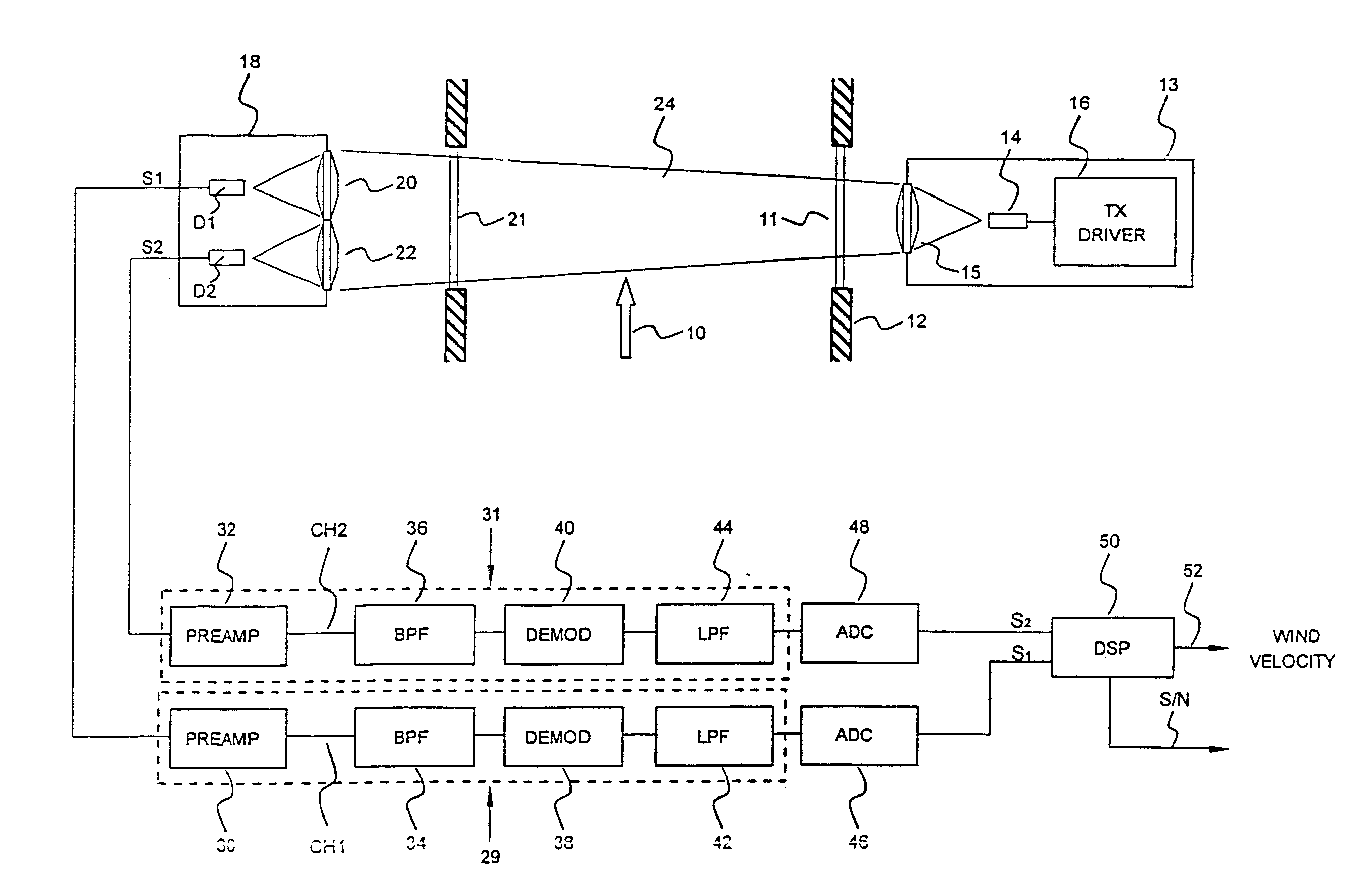
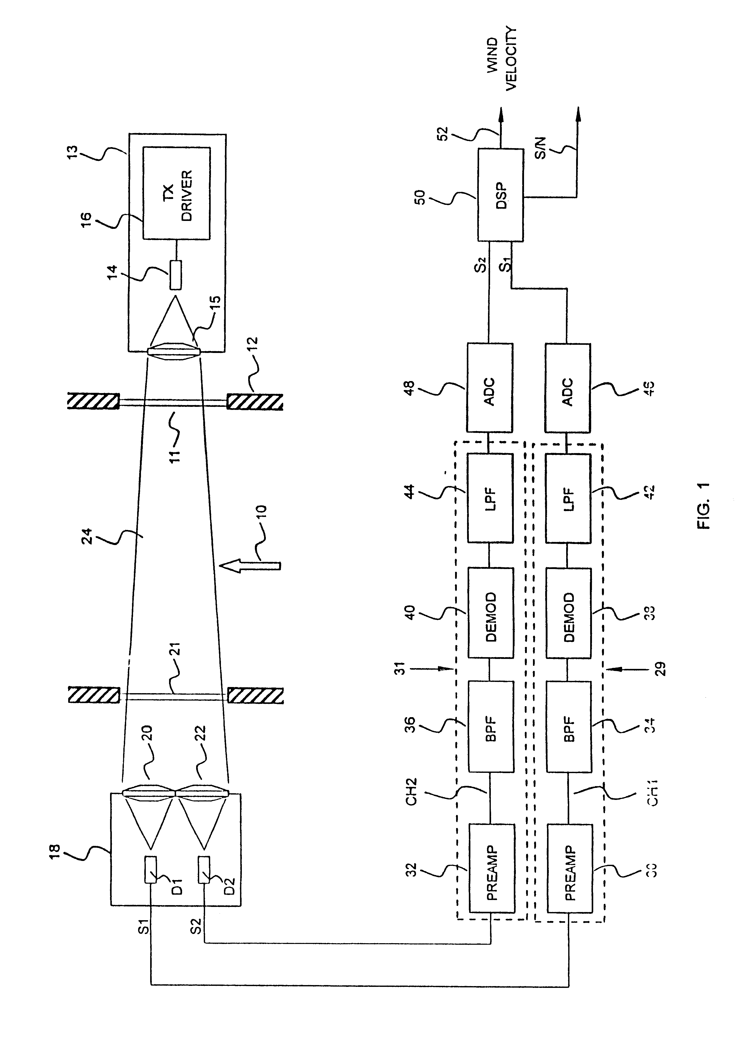
FIGS. 1-6 illustrate the major equipment components of a preferred embodiment of an optical flow sensor of the present invention as described in prior U.S. application Ser. No. 09 / 574,322, filed May 19, 2000, which is hereby incorporated by reference in its entirety. FIG. 1 illustrates diagrammatically an optical flow sensor for measuring gas flow velocity in a predetermined linear direction, indicated by the arrow 10 within an elongated, vertically oriented chimney 12 which may, for example, have a diameter of about 10 feet and a length of 30 feet or more. Only a short section of the chimney 12 is shown in FIG. 1.

The optical flow sensor includes a transmitter 13 having a laser diode or an LED 14 located in front of the chimney window 11 and driven by a transmitter driver 16. The transmitter 13 includes an optically transparent collimating lens 15. A receiver 18 is located on the wall of the chimney 12 diametrically opposite the transmitter 13, and includes a pair of receiving lense...


PUM


Abstract

An optical flow sensor determines the velocity of a moving flow of air or other gas utilizing a plurality of photodetectors spaced apart in a direction parallel to the direction of gas flow. An optical beam is transmitted to the photodetectors across the flowing gas. Scintillations that occur in the flowing gas due to eddies and particulates in the gas are detected in the photodetectors at slightly different times. The output signals of the photodetectors are conditioned, amplified and transformed to digital form. Temporal cross correlation analysis is then performed on the digitized signals in a digital signal processor utilizing a fast correlation algorithm in which the total number of calculations is proportional to 2N, as contrasted with conventional systems in which the number of correlations is proportional to N2. A time differential between signals from the different photodetectors is then calculated electronically. The velocity of gas flow is then determined by dividing the spatial distance of separation between adjacent photodetectors by the time difference at which the same scintillation event is detected by each photodetector.

Description

1. Field of the InventionThe present invention relates to an optical flow sensor which cross correlates digitized signals from a plurality of photodetectors that are separated in a direction parallel to a predetermined direction of gas flow and to a method of determining gas flow velocity in a predetermined direction.2. Description of the Prior ArtAccurate flow rate measurement represents one of the biggest problems in industrial and environmental monitoring for contaminants in gaseous discharges. The problem of airborne pollution has become so acute that virtually all industries of any size are now monitored for compliance with applicable regulations or laws limiting gaseous discharges. While the determination of the concentration of pollutants, contaminants, noxious gases, and toxic gases in a gas flow has reached a satisfactory level of reliability, monitoring of the rate, and hence the volume of gas flow, has heretofore been rather inaccurate. As a consequence. The determination...

Claims


Application Information

Patent Timeline
Patent Type & Authority Patents(United States)
IPC IPC(8): G01F1/712G01F1/704G01F1/708G01P5/18G01P5/22G01P5/26G01P5/00G01F1/7086
CPCG01F1/7086G01F1/712G01P5/22G01P5/26
Inventor WANG, TING-I
Owner OPTICAL SCI
Why Eureka
Try Eureka