
Method and apparatus for puncturing code symbols in a communications system

a communication system and code symbol technology, applied in the field of data communication, can solve the problems of compromising performance and more symbols being punctured

Inactive Publication Date: 2003-09-02
QUALCOMM INC
View PDF6 Cites 6 Cited by
  • Summary
  • Abstract
  • Description
  • Claims
  • Application Information

AI Technical Summary

Benefits of technology

The symbol puncturing can be achieved by (1) selecting either the puncture distance of D1 or D2 to be used to determine which symbol should be punctured next, (2) puncturing the next symbol based on the selected puncture distance, and (3) decrementing P1 or P2 based on the selected puncture distance. Steps (1) through (3) can be repeated until all P1 and P2 symbol punctures are achieved. The puncture distance can be selected such that the P1 symbol punctures at the distance of D1 are distributed among the P2 symbol punctures at the distance of D2. For example, if the ratio of P1 to P2 is equal to R, then the puncture distance can be selected such that, on an average, R symbol punctures are performed at the distance of D1 for each symbol puncture at the distance of D2. Alternatively, P1 symbol punctures at the distance of D1 can be performed, followed by P2 symbol punctures at the distance of D2. The method can thus be used to provide a rich set of patterns of puncture distances D1 and D2 that can provide improved performance.

Problems solved by technology

In certain situations, this method can puncture symbols unevenly throughout an entire frame, which results in more symbols being punctured in one portion of the frame and less or no symbols being punctured in some other portion of the frame.
When symbols are unevenly punctured, performance may be compromised.

Method used


Image

  • Method and apparatus for puncturing code symbols in a communications system
  • Method and apparatus for puncturing code symbols in a communications system
  • Method and apparatus for puncturing code symbols in a communications system

Examples


Embodiment Construction

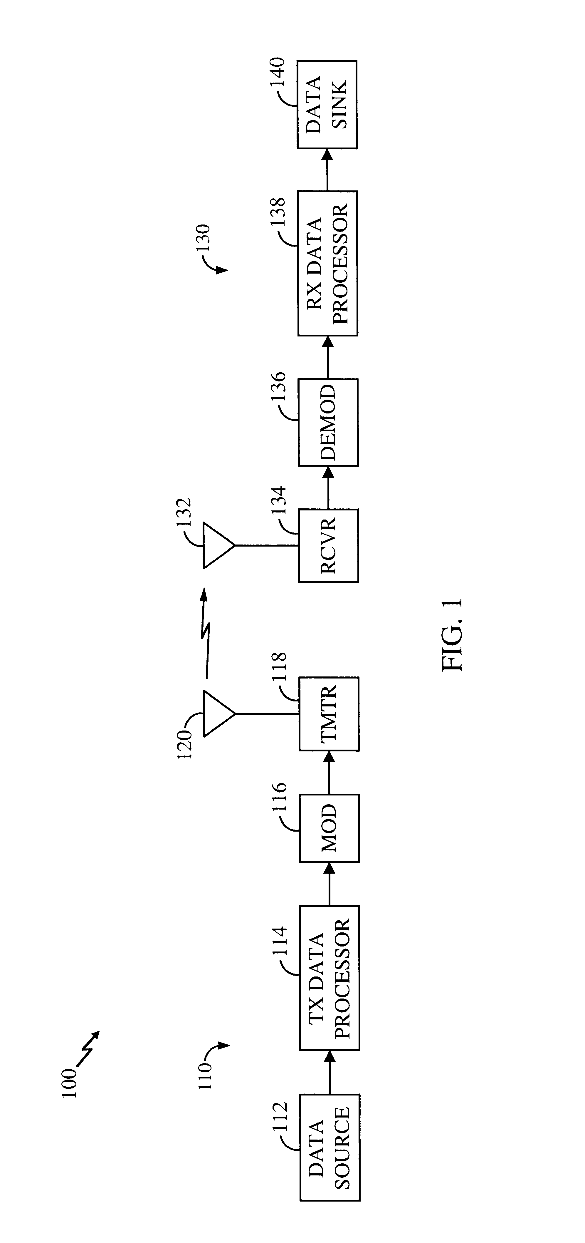
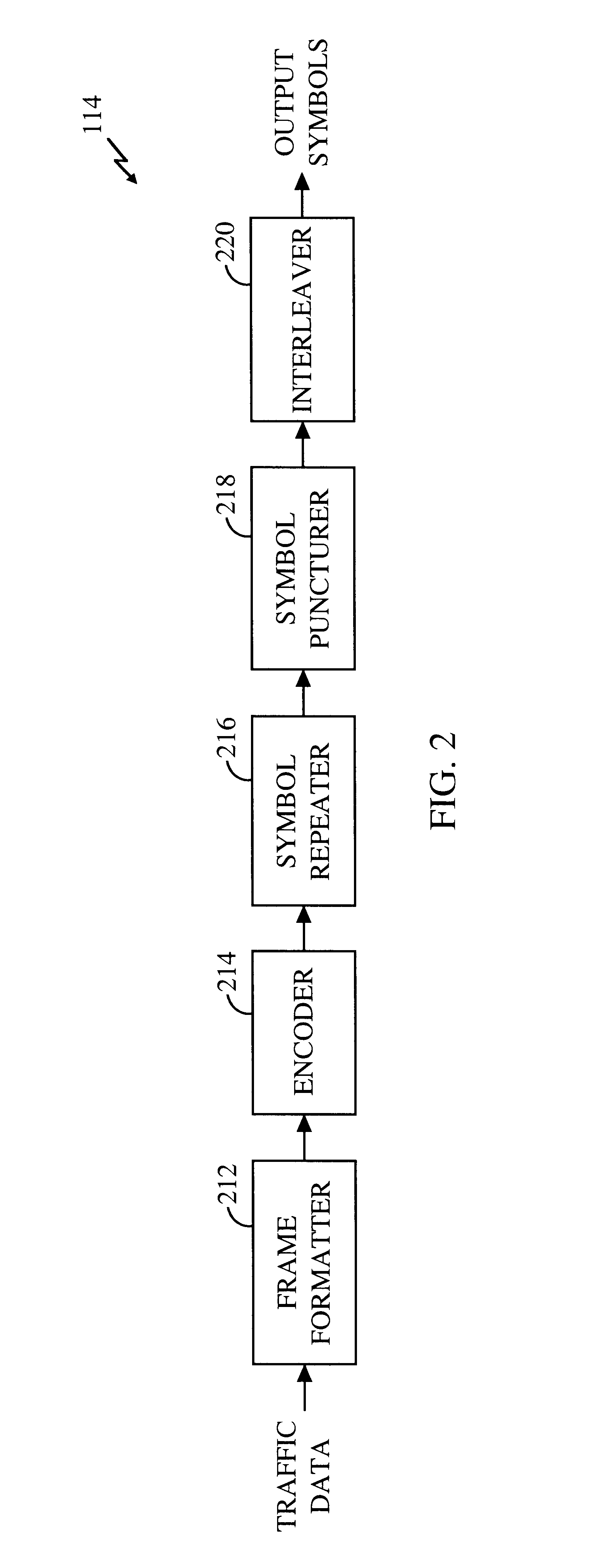
FIG. 1 is a simplified block diagram of an embodiment of a communications system 100 in which the present invention may be implemented. At a transmitter unit 110, traffic data is sent, typically in frames or packets, from a data source 112 to a transmit (TX) data processor 114 that formats, encodes, and interleaves (i.e., reorders) the data in accordance with a particular processing scheme. TX data processor 114 typically further processes signal and control data (e.g., pilot and power control data). A modulator (MOD) 116 then receives, channelizes (i.e., covers), and spreads the processed data to generate symbols that are then converted to analog signals. The analog signals are filtered, quadrature modulated, amplified, and upconverted by a transmitter (TMTR) 118 to generate a modulated signal, which is then transmitted via an antenna 120 to one or more receiver units.

At a receiver unit 130, the transmitted signal is received by an antenna 132 and provided to a receiver (RCVR) 134....


PUM


Abstract

Techniques for puncturing symbols in a communications system. S symbols are received for a frame having a capacity of N symbols, with S being greater than N. P symbols need to be punctured so that remaining symbols fit into the frame. A number of puncture distances, D1 through DN, are computed based on S and P. A particular number of symbol punctures is determined for each computed puncture distance. P1 through PN symbol punctures are then performed at the distances of D1 through DN, respectively. For a more even distribution of the symbol punctures, each of the distances D1 through DN can be selected to be greater than or equal to a minimum puncture distance Dmin defined as Dmin=└S / P┘, where └ ┘ denotes a floor operator. The symbol punctures at each computed distance can be performed together or distributed with symbol punctures at other distances. In the alternative, an accumulator is configured to wrap around after it has been incremented to a value of S, each increment being of size P. A symbol index is incremented by one each time the accumulator is incremented by P, until the symbol index exceeds the value S. The process is advantageously begun with a puncture. Each time the accumulator wraps around, another puncture is performed.

Description

I. Field of the InventionThe present invention relates to data communications. More particularly, the present invention relates to a method and apparatus for puncturing code symbols to provide improved performance in a communications system.II. Description of the Related ArtIn a typical digital communications system, data is processed, modulated, and conditioned at a transmitter unit to generate a modulated signal that is then transmitted to one or more receiver units. The data processing may include, for example, formatting the data into a particular frame format, encoding the formatted data with a particular coding scheme to provide error detection and / or correction at the receiver unit, puncturing (i.e., deleting) some of the code symbols to fit within a particular frame size, channelizing (i.e., covering) the encoded data, and spreading the channelized data over the system bandwidth. The data processing is typically defined by the system or standard being implemented.At the rece...

Claims


Application Information

Patent Timeline
Patent Type & Authority Patents(United States)
IPC IPC(8): H04L1/08H03M13/00H04L1/00
CPCH04L1/0041H04L1/0068H04L1/08H04L1/0059H04L1/0071
Inventor RAZOUMOV, LEONIDLING, FUYUN
Owner QUALCOMM INC
Features
  • Generate Ideas
  • Intellectual Property
  • Life Sciences
  • Materials
  • Tech Scout
  • Unparalleled Data Quality
  • Higher Quality Content
  • 60% Fewer Hallucinations
Learn More