Rotary pump with bearing wear indicator

a technology of bearing wear indicator and rotary pump, which is applied in the direction of rotary/oscillating piston pump components, machines/engines, liquid fuel engines, etc. it can solve the problems of excessive wear detection device, increased vibration of the pump housing, and failure to occur even short-term, so as to prevent catastrophic failure, increase the vibration of the pump housing, and reduce the effect of wear

Inactive Publication Date: 2003-09-09
AIR & LIQUID SYST LLC
View PDF13 Cites 43 Cited by
  • Summary
  • Abstract
  • Description
  • Claims
  • Application Information

AI Technical Summary

Benefits of technology

The present invention relates to the concept of detecting wear of the conical bearings to determine when they should be replaced and/or refurbished. Consequently, frequent inspection of the bearings is not necessary. Bearings are given attention only when actually needed. This is a substantial advantage, is cost effective and prevents catastrophic failure based upon bearing malfunction. In the past, such failure could occur between even short term inspections. The invention involves an improvement in a rotary pump of the type described and incorporated by reference herein. Real time monitoring of the conical bearing wear is the result of using the invention. An excessive wear detecting device uses an imbalance member that is associated with each of the axially spaced conical bearings. The imbalance ring or plate (i.e. member) surrounds the shaft and includes a drive member axially spaced outwardly from a drive member on the rotating shaft. As the bearing being monitored is subject to wear, the two drive members move together and ultimately engage. This causes the shaft to rotate the imbalance member to drastically increase the vibration of the pump housing. A sensor detects the drastic increase in the housing vibration to indicate bearing wear at a m...

Problems solved by technology

In the past, such failure could occur between even short term inspections.
An excessive wear detecting device uses an imbalance member that is associated with each of the axially spaced conical bearings.
As the bearing being monitored is subject to wear, the two drive members move together and ultimately engage.
This causes the shaft to rotate the imbalance member to drastically increas...

Method used


Image

  • Rotary pump with bearing wear indicator
  • Rotary pump with bearing wear indicator
  • Rotary pump with bearing wear indicator

Examples


Embodiment Construction

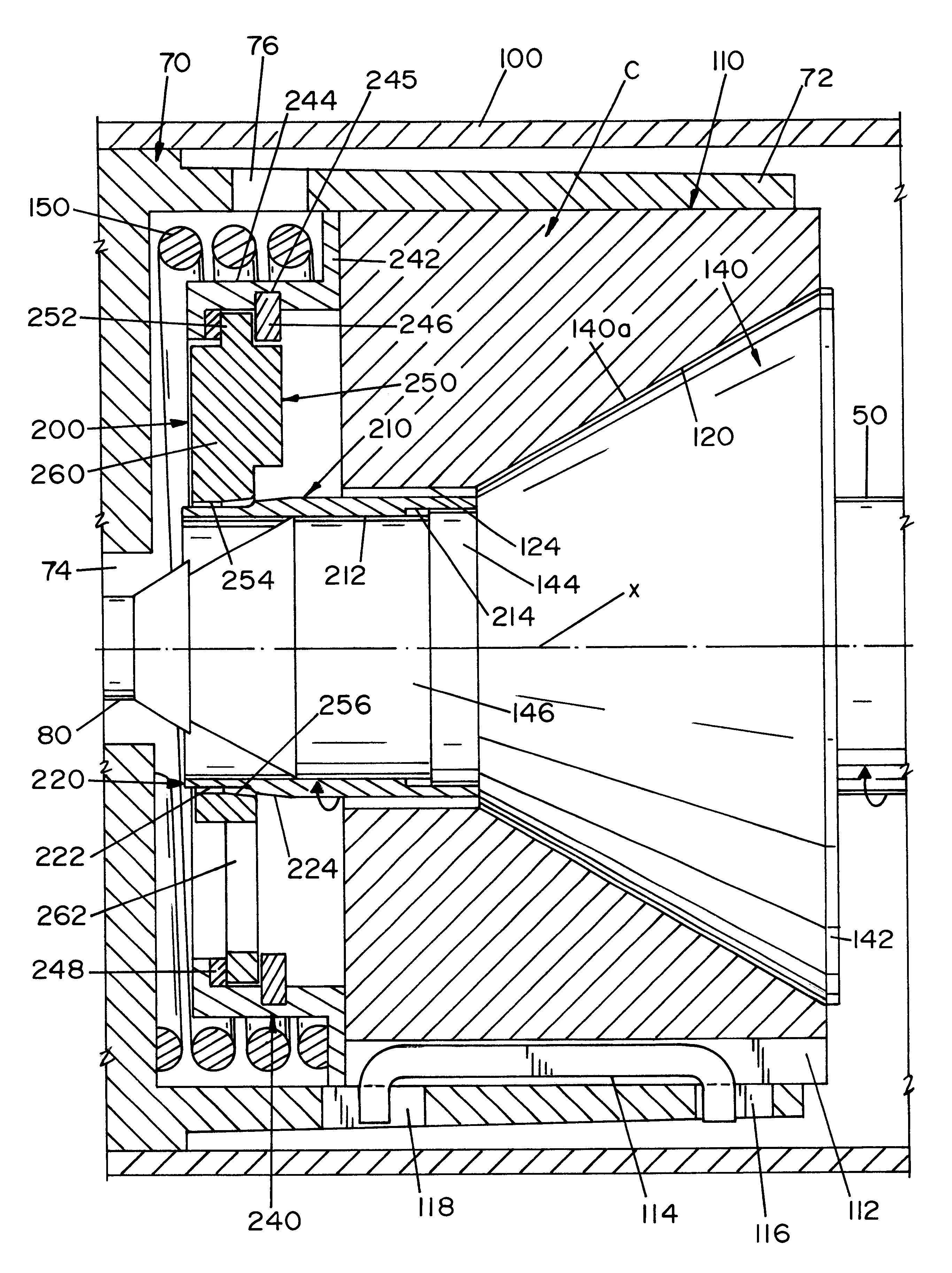
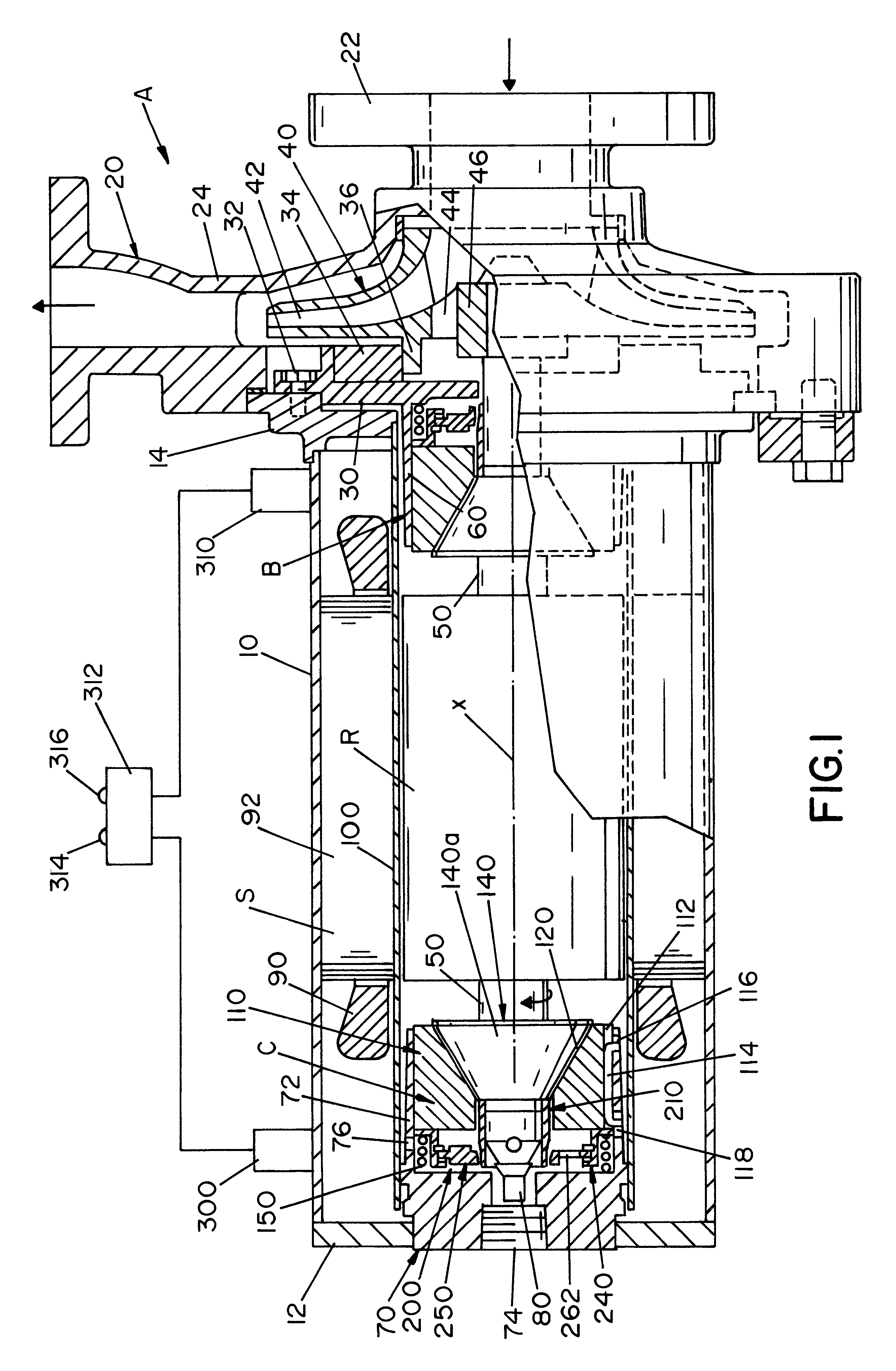
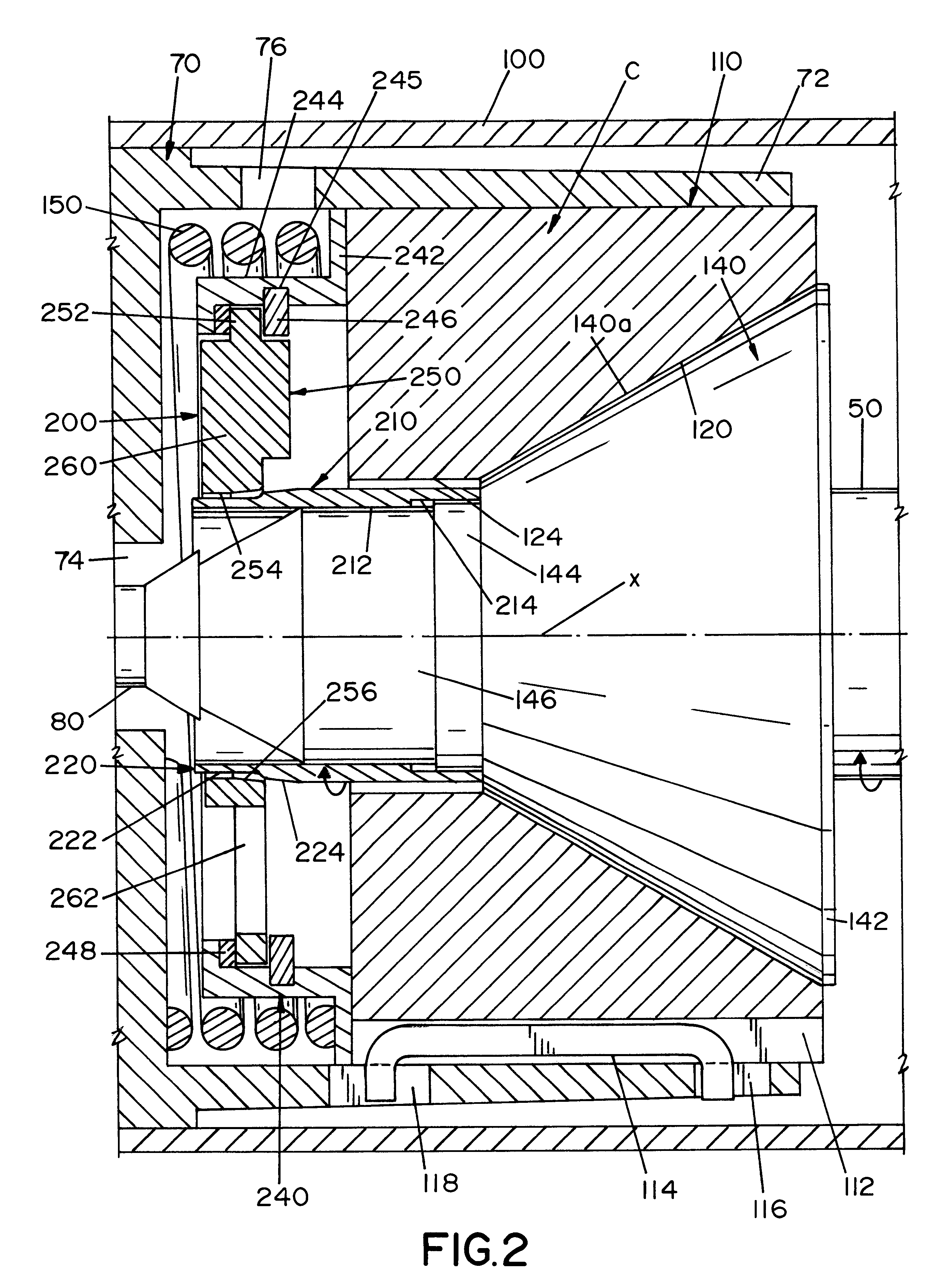
Referring now to the drawings wherein the showings are for the purpose of illustrating the preferred embodiment of the present invention and not for the purpose of limiting same, FIG. 1 shows a rotary pump A with a vibration inducing bearing wear monitoring assembly installed on each of the conical bearings B and C. A simple base line pump vibration measurement during the initial start up is required. This gives the normal vibration level for pump A. Periodic monitoring of the pump will indicate by means of increased vibration readings when conical bearings B and C require inspection or replacement. As will be explained later, a vibration cage assembly, which is constructed of a non-corrosive material, is installed between each of the standard coiled springs and the conical bearings B and C while a tapered sleeve is fitted over the shaft. An imbalance member floats freely within the cage assembly while the bearings maintain axial balance. As the conical bearing wears, one element mo...


PUM


Abstract

A rotary pump for liquid having a housing, a shaft carrying a motor rotor, a motor stator fixed in the housing and surrounding the rotor to rotate the rotor and shaft about an axis. The shaft is mounted in the pump housing by axially spaced conical bearings, each bearing including a first element fixed on the shaft with a first conical bearing surface concentric with the axis, a coacting second element carried by the housing with a second conical bearing surface concentric with the axis and slidably engaging the first bearing surface and a spring forcing the elements together. This pump includes a wear indicator comprising: a first drive member on the shaft, an imbalance member carried with the second element of a bearing with a second drive member aligned with the first member and movable axially toward the first drive member as the bearing surfaces wear so the first and second drive members engage when the imbalance member moves axially a given distance. A sensor detects vibrations caused by rotation of the imbalance member by the shaft.

Description

The present invention relates to a rotary pump for liquid and more particularly to a rotary pump of the immersed rotor type with a bearing wear indicator.INCORPORATION BY REFERENCEThe present invention is particularly applicable to a liquid rotary pump where the liquid immerses the motor rotor that is isolated from the motor stator by a shield, often referred to as a "can" or "jacket." This type of pump has been manufactured for many years and includes a shaft for rotatably mounting the rotor of the motor driving the pump. To center the rotor in the pump housing it has proven quite beneficial to use a mechanism having axially spaced conical bearings. Such a pump and bearings are disclosed in Young U.S. Pat. No. 3,195,466. Conical shaft bearings not only center the rotor and maintain the axial position of the pump impeller, but also provides the friction surfaces between the pump housing and the rotating elements within the pump. Young U.S. Pat. No. 3,195,466 is incorporated by refer...

Claims


Application Information

Patent Timeline
IPC IPC(8): F04D29/04F04D29/041F04D29/047F16C17/10F16C17/14F16C17/24F16C25/04F16C41/00
CPCF04D29/0413F04D29/047F16C17/24F16C17/10F04C29/00
Inventor GOODNICK, DOUGLAS J.LINEHAN, PATRICK R.REASINGER, JOSEPH D.
Owner AIR & LIQUID SYST LLC
Why Eureka
Try Eureka