Method for a removal of cathode depositions by means of bipolar pulses

a technology of cathode deposition and bipolar pulse, which is applied in the direction of manufacturing tools, power source circuits, electric circuits machining, etc., can solve the problems of inferior accuracy of electrochemical machining, deviation of effective geometrical shape of cathode, and inability to control the removal process of cathode deposition

Inactive Publication Date: 2003-09-16
KONINKLIJKE PHILIPS ELECTRONICS NV
View PDF4 Cites 6 Cited by
  • Summary
  • Abstract
  • Description
  • Claims
  • Application Information

AI Technical Summary

Problems solved by technology

The disadvantage of the known method is the fact that the process of the removal of cathode depositions is not controlled, as there is no information available in the system upon the extent of the cathode depositions.
Therefore, it is possible that the surface of the cathode is not completely cleaned, leading to deviations in the effective geometrical shape of the cathode.
This results in an inferior accuracy of the electrochemical machining.
This phenomenon is pronounced especially under conditions of difficult evacuation of the products of chemical reactions taking place in the gap.
In these conditions, the operating conditions are not favorable for the cathode depositions to be generated to a great extent, resulting in a minor variations in the value of the cathode potential.

Method used


Image

  • Method for a removal of cathode depositions by means of bipolar pulses
  • Method for a removal of cathode depositions by means of bipolar pulses
  • Method for a removal of cathode depositions by means of bipolar pulses

Examples


Embodiment Construction

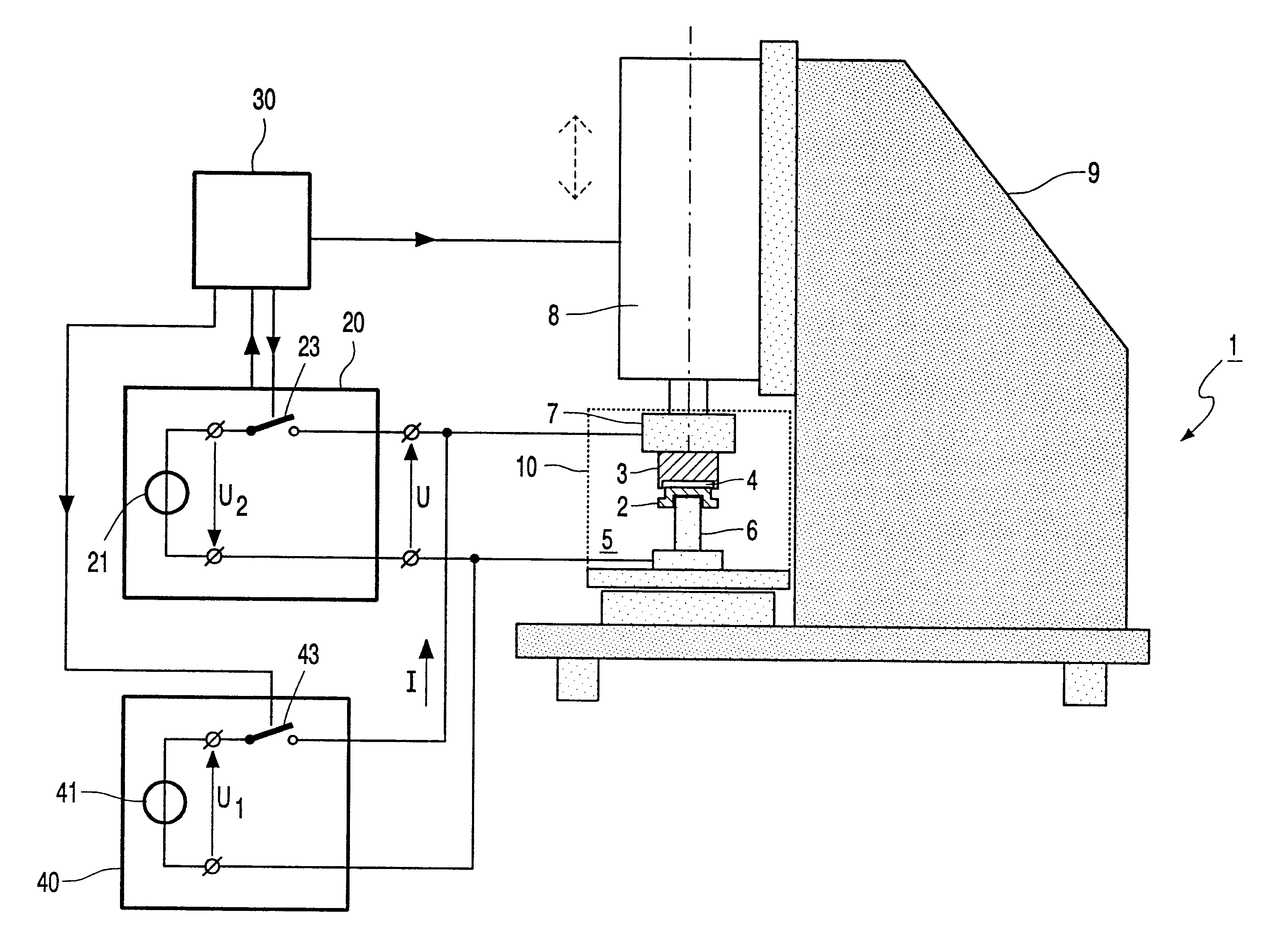
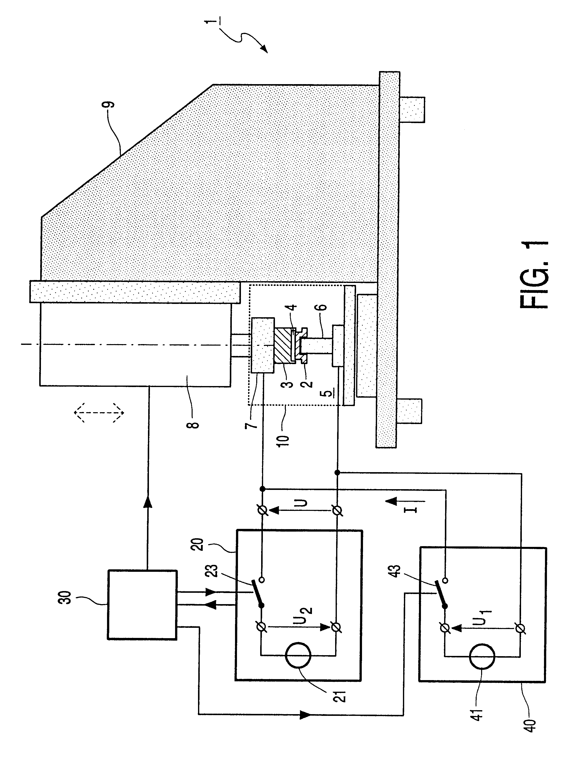
FIG. 1 presents a schematic view of an arrangement 1 for electrochemically machining of an electrically conductive work piece 2 by means of an electrode 3. The arrangement 1 comprises a base 6 for positioning a work piece 2, a holder 7 for positioning an electrode 3, and an actuator 8 for moving the holder 7 and the base 6 with respect to one another. The base 6 and the actuator 8 are mounted on a chassis 9 having a rigid construction so as to enable a working distance between the electrode 3 and the work piece 2 to be set with a high accuracy. The arrangement comprises further a reservoir 10 filled with an electrolyte 5 in such a manner that the gap 4 formed as a result of the working distance between the electrode 3 and the work piece 2 is filled with the electrolyte 5. In the present case, the electrolyte comprises NaNO.sub.3 dissolved in water. As an alternative it is possible to use another electrolyte, such as for example NaCl or a combination of NaNO.sub.3 and an acid. The el...


PUM

PropertyMeasurementUnit
surface roughnessaaaaaaaaaa
electrically conductiveaaaaaaaaaa

Abstract

A method for on-line removal of cathode depositions during electrochemical process. The process control unit (30) is arranged to alternate the unipolar machining voltage pulses U1 with the voltage pulses of opposite polarity U2 to the work piece (2) and the cathode (3). The process control unit comprises an arrangement to determine the amount of cathode depositions on-line based on the operational parameter. Only in case the operational parameter exceeds the allowable level, the process control unit (30) alternates the unipolar machining voltage pulses U1 with the voltage pulses of opposite polarity U2. In this case the cathode wear is minimized.

Description

1. Field of the InventionThe invention relates to a method of electrochemically machining an electrically conductive work piece in an electrolyte by applying bipolar electric pulses between the work piece and an electrically conductive electrode, one or more voltage pulses of unipolar machining polarity being alternated with voltage pulses of opposite polarity, while a gap between the work piece and the electrode is maintained, which gap is filled by the electrolyte.The invention further relates to an arrangement for electrochemically machining of an electrically conductive work piece in an electrolyte by applying bipolar electric pulses between the work piece and an electrode, one or more voltage pulses of unipolar machining polarity being alternated with voltage pulses of an opposite polarity, while a gap between the work piece and the electrode is maintained, which gap is filled by the electrolyte.2. Description of the Related ArtElectrochemical machining is a process in which an...

Claims


Application Information

Patent Timeline
Patent Type & Authority Patents(United States)
IPC IPC(8): B23H3/02B23H3/00B23H7/20
CPCB23H3/02B23H2300/12B23H2300/10
Inventor ZAITSEV, ALEXANDRGIMAEV, NASICH ZIJATDINOVICHKUTSENKO, VOCTORAMIRCHANOVA, NAILYA A.BELOGORSKY, ALEKSANDR LEONIDOVICHMARKELOVA, NATALYAMUCHUTDINOV, RAFAIL RAMZISOVICHBRUSSEE, MAARTEN
Owner KONINKLIJKE PHILIPS ELECTRONICS NV
Why Eureka
Try Eureka