
Can seam forming apparatus

a technology of seam forming and cannon, which is applied in the direction of apparatus for force/torque/work measurement, instruments, measurement devices, etc., can solve the problems of inability to meet the needs of use, and inability to withstand the pressure of the internal air, so as to reduce the risk of cam failure, reduce the set-up time, and be reliable and economical to operate.

Inactive Publication Date: 2003-09-23
PNEUMATIC SCALE CORP
View PDF10 Cites 16 Cited by
  • Summary
  • Abstract
  • Description
  • Claims
  • Application Information

AI Technical Summary

Benefits of technology

It is a further object of the present invention to provide a double seam forming apparatus that minimizes the risk of false fault indications.
The preferred form of the invention also includes a reject portion which is operative to divert cans that have been flagged because they exhibit a fault condition. The reject portion is operative to divert such cans after they have passed through the machine so as to segregate defective cans from good cans without having to shut down the apparatus.

Problems solved by technology

The sealing of cans is important because an improper seal may result in the infiltration of air to the interior of the can.
This may result in bacterial growth and premature spoilage.
Unfortunately this is not always possible.
Undesirable conditions may occur due to defects in either the can body or the can end.
Such defects may include undesirable variances in dimensions in which the ends do not perfectly "fit" the can bodies.
Other conditions which may cause imperfect seams include cracks or tears in the can bodies or can ends.
Such defects may result in loose or open spaces in the seam.
Similarly, defective manufacture of the ends or bodies may result in folds or areas having excessive metal thickness.
Such defects in the area of the seam also prevent proper seam formation.
Defects in the chucks or rolls which are used to form the seams can also result in defective can seams.
Such defects may include the accumulation of metal on a chuck or roll.
The accumulated material causes irregularity in the tooling surface in contact with a seam as it is being formed and can result in an improper seam.
Alternatively the-chucks or rolls used to form the seam may crack, producing a gap.
The seam is not properly formed in the area of the gap which results in improper can closure.
If a tooling problem occurs at one chuck or roll, it will not be readily apparent because only cans that have been acted upon by the defective tooling will exhibit an improper seam.
It is therefore difficult to detect a problem as soon as it occurs.
Common defects include situations where the seam is either too tight or too loose.
Such defects may arise in the form of a consistently high or low force or a transient force "spike".
While the device shown in U.S. Pat. No. 4,600,347 represents a significant advance in the detection of seaming problems, it suffers from several drawbacks.
These drawbacks include the fact that double seam forming can closing machines generally include many stations.
The prior art devices cannot account for this variation in normal loading between the various machine stations.
An improper fault indication may result if the limits are set too narrowly.
However, if the limits are set too widely then defective cans may be allowed to pass.
A further drawback associated with the prior art is that force variations that result from excess metal or a broken seam or chuck, are only detected if the corresponding spike is sufficiently "high" or "low" to extend beyond the limits which are established for a tight or a loose seam.
Spikes or breaks that occur within the limits may be indicative of a developing tooling problem and / or have adverse consequences for the seam.
However, in the prior art such conditions may go undetected.
A further drawback associated with the prior art is that developing problems with tooling, can bodies and can ends often go undetected until one of the limits is exceeded.
Such movement of seam conditions away from the optimum, increases the risk of seam failure.
Unfortunately because the prior art devices cannot account for variations from station to station, such trends are difficult to detect.
As a result if a single can exhibits a fault condition, it is necessary to either shut the machine down or to locate the defective can among a large population of good cans.
Stopping the machine delays production which increases costs and requires a set-up person's attention for restart.
Alternatively, not shutting the machine down while attempting to locate the can that is defective may be very time consuming.
Visual inspection often may not readily distinguish a defective can which further complicates the problem.
A further drawback associated with the prior art systems is that they may be subject to false triggering.
Vibration or other conditions may result in short-term "noise" from the sensors on the stationary cam.
This noise may produce a signal which falls outside the high and low limits, which causes a fault indication to be given.
A further drawback associated with such prior art systems is the time necessary to set up the system.
This task is complicated by the fact that sensor signals for a good seam can vary from station to station as previously discussed.
This process of observing seam profiles for numerous documented good seams at each of the numerous stations on the double seam forming machine is time consuming.
A further drawback associated with the prior art systems is that the instrumented portion of the cam is ideally relatively flexible compared to other portions of the cam.
Making the instrumented portion of the cam more flexible also reduces its strength.
There is a risk that the instrumented cam portion may fracture or take on a permanent set due to the application of excessive force.
Such excessive force may result from a situation where additional metal is present on a can, roll or chuck.
Damage to the cam generally necessitates cam replacement.
This is costly and time consuming.
Further costs may be associated with production downtime.

Method used


Image

  • Can seam forming apparatus
  • Can seam forming apparatus
  • Can seam forming apparatus

Examples


Embodiment Construction

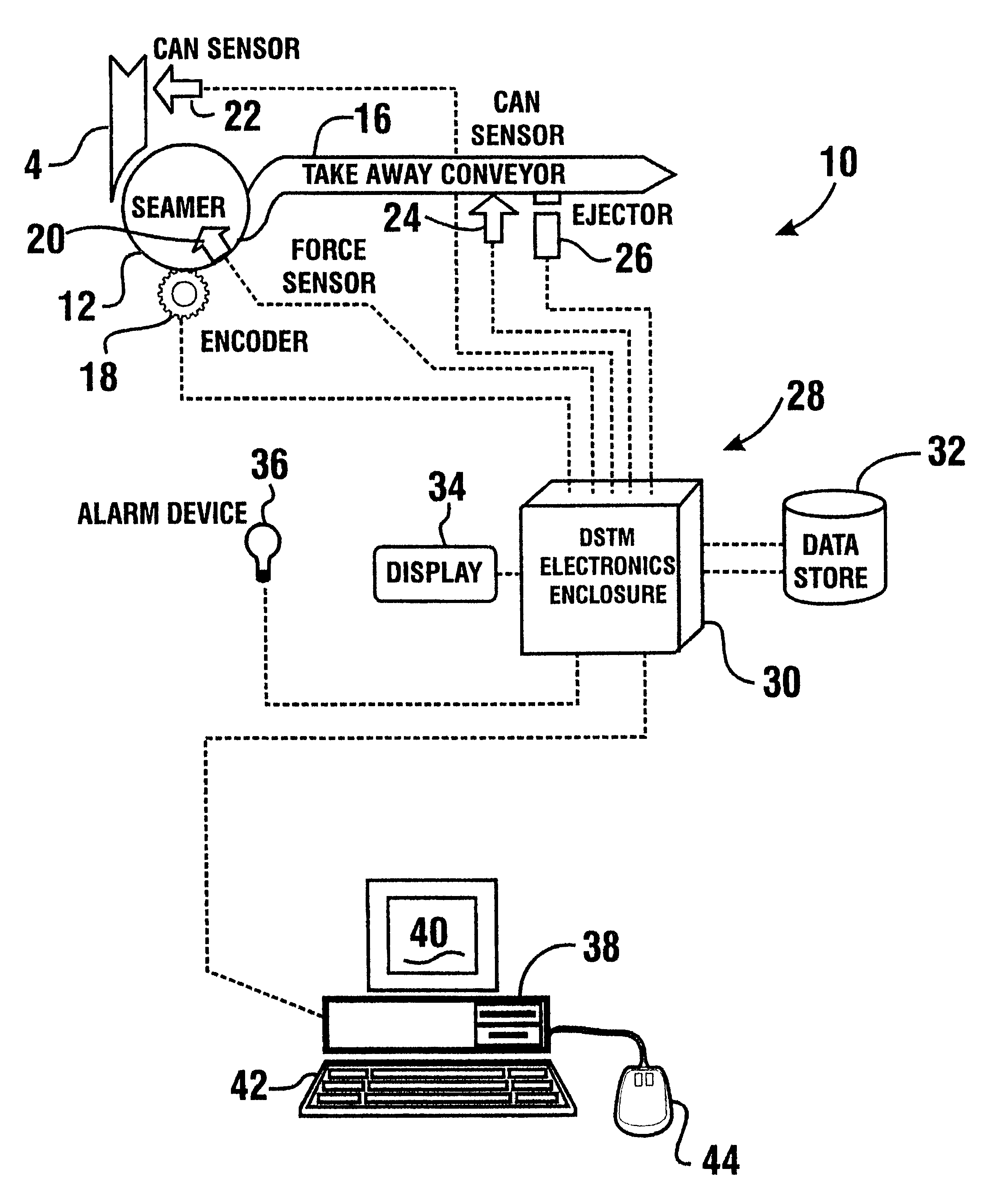
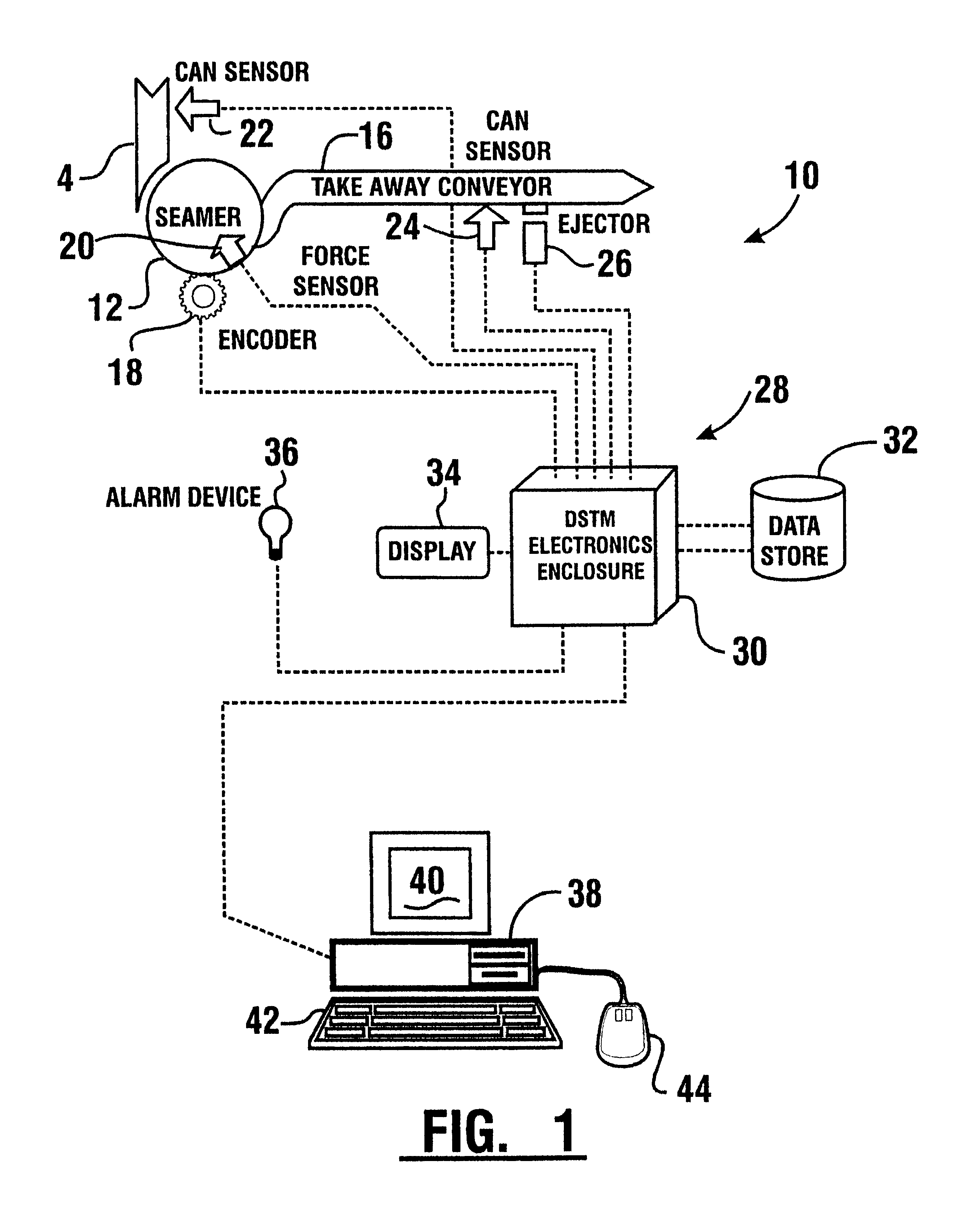
Referring now to the drawings and particularly to FIG. 1, there is shown therein a schematic view of an embodiment of the apparatus of the present invention generally indicated 10. The apparatus includes a double seam forming can seamer 12. In the preferred form of the invention seamer 12 is of the type that attaches can ends on to can bodies through formation of a hermetic folded double seam. The seamer may be of a type shown in U.S. Pat. No. 3,465,703 which performs first and second seaming operations to form a circumferential seam. The seamer preferably includes a plurality of stations. For purposes of this illustrative embodiment the seamer includes six (6) stations. Of course, seamers with different numbers of stations may alternatively be used.

The apparatus 10 is in operative connection with a feed conveyor 14. Feed conveyor 14 feeds open can bodies preferably containing a product to seamer 12. A take-away conveyer 16 carries away the cans upon which the ends have been install...


PUM

PropertyMeasurementUnit
forceaaaaaaaaaa
threshold valueaaaaaaaaaa
thresholdaaaaaaaaaa

Abstract

A double seam forming apparatus for applying end units to can bodies includes a can seamer (12) with a seaming cam (46). Seaming cam (46) includes a high dwell portion (56) which deforms responsive to force encounterred by tooling during forming of a can seam. A reinforcing pin (72) limits deformation of the high dwell portion to prevent damage. The high dwell portion of the cam includes a force sensor (20) which generates a signal responsive to strain of the high dwell portion due to applied force. The apparatus further includes a monitor apparatus (28). The monitor apparatus includes a controller (30) which includes a processor and a data store (32), and a host station (38). The monitor apparatus is operative to identify seam fault conditions and to store data concerning seamer conditions. The monitor apparatus also operates a can ejector (26) to divert cans identified as having defective seams.

Description

This invention relates to can closing machines. Specifically this invention relates to a double seam forming can closing apparatus which identifies defects and rejects cans with improper seams. This invention further relates to a double seam forming can closing apparatus in which the seam forming parameters may be set up more rapidly and reliably.Canning equipment and processes are commonly used in a variety of industries. Canning processes are often used to preserve food products because such products can be processed and promptly hermetically sealed within a can. Canning operations may be performed at high speed and at a reasonable cost. The sealing of cans is important because an improper seal may result in the infiltration of air to the interior of the can. This may result in bacterial growth and premature spoilage.Can closing machines are known in the prior art. One type of can closing machine secures an end to a can body after the product has been placed in the can by formatio...

Claims


Application Information

Patent Timeline
Patent Type & Authority Patents(United States)
IPC IPC(8): B21D51/30B21D51/32G01L5/00
CPCB21D51/30B21D51/32G01L5/0076
Inventor BAGHERI, ALIBERNSTEIN, JEFFREY K.
Owner PNEUMATIC SCALE CORP
Learn More