Angle grinder with electric drive

a technology of electric drive and angle grinder, which is applied in the direction of manufacturing tools, portable power-driven tools, windings, etc., can solve the problems of dimensional stability, large assembly effort, and large assembly cost, and achieves the effect of dimensional stability, high precision and high cos

Inactive Publication Date: 2003-10-14
ROBERT BOSCH GMBH
View PDF11 Cites 36 Cited by
  • Summary
  • Abstract
  • Description
  • Claims
  • Application Information

AI Technical Summary

Benefits of technology

The angle grinder of the invention having the characteristics of claim 1 has the advantage of especially favorable production costs.Because the housing comprises two longitudinally split housing shells, and the brush plates are part of a bearing bridge that carries both the rotor bearing and the carbon brushes, and the bearing bridge, in the guide region of the carbon brushes, comprises plastic, the precision of the relationship of the rotor bearing and the carbon brushes can be attained better and more simply.Because the guide region of the carbon brushes is designed as a shaft of square cross section and one of the four sides of the shaft is of metal, in particular sheet brass, the walls of the shaft can be dimensioned as relatively thin, yet the mechanical load-bearing capability is especially high, especially because of the forces that are operative in the rotational direction of the motor between the collector and the carbon brushes when the angle grinder is used as intended.Because the cord of the carbon brushes can be held firmly in indentations of the bearing bridge, and in particular can be clamped with a rubber stopper, an economical standard carbon brush can be used in conjunction with the bearing bridge.Because the cord has a plug on its free end, which in particular is crimped onto this end and can be locked releasably in detent fashion to the bearing bridge, the carbon brush is easy to replace.Because the bearing bridge has an integrated switch, which is provided with means that force the switch open as the toggle switch is switched off, an unwanted closure of the switch and the attendant adverse consequences, such as oxidation of the collector, are precluded.Because the bearing bridge carries the rotor bearing set in a rubber bush, low-vibration operation of the angle grinder is assured.

Problems solved by technology

This type of arrangement is relatively complicated and requires major effort of assembly as well as expensive, dimensionally stable housing parts.

Method used


Image

  • Angle grinder with electric drive
  • Angle grinder with electric drive
  • Angle grinder with electric drive

Examples


Embodiment Construction

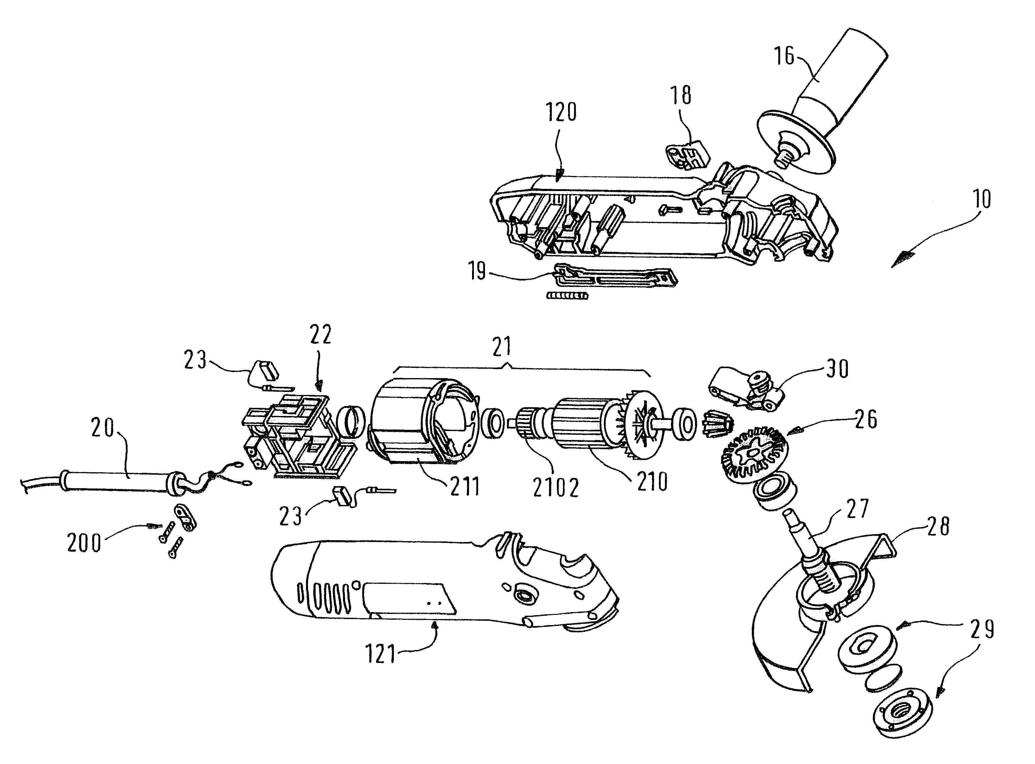
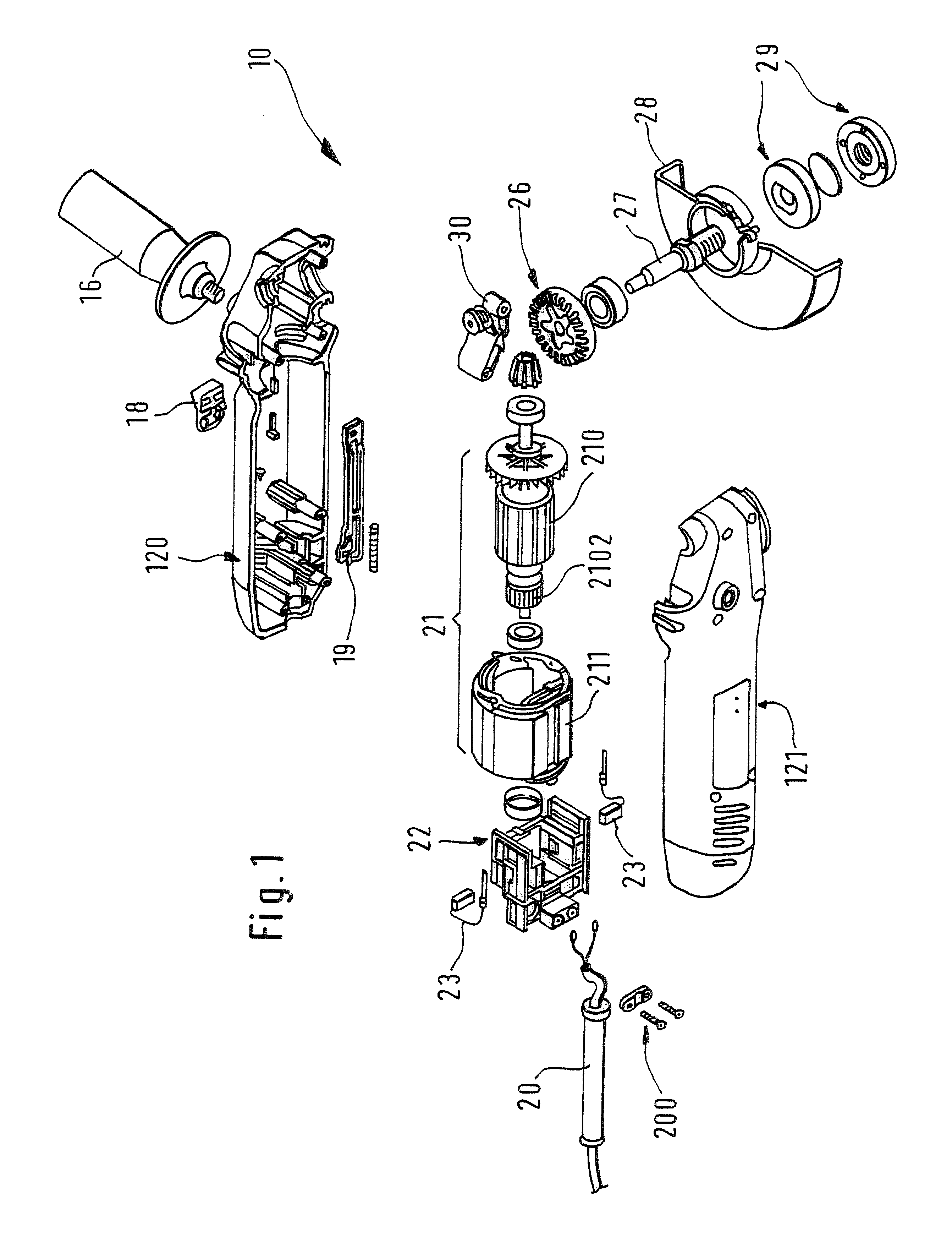
FIG. 1 shows an exploded view of a power tool designed as an angle grinder. Its housing 12 comprises a first and second housing shell 120, 121. The first housing shell 120 has a longitudinally displaceable toggle switch 18 on the side, for actuating a switch 15. The first housing shell 120 also has an extra handle 16 for additionally holding and guiding the angle grinder with the second hand.

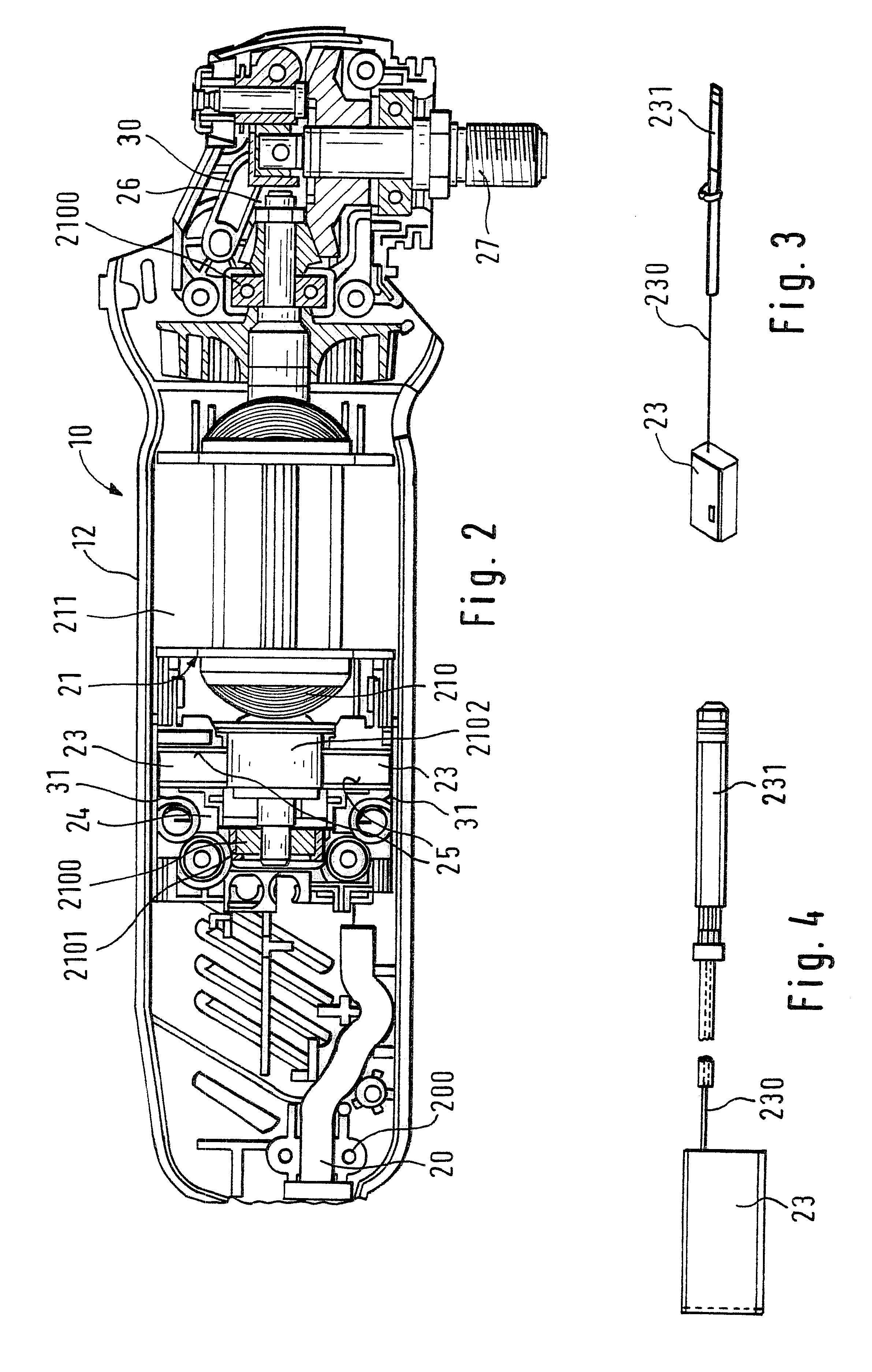
The toggle switch 18 is coupled to a switch 15 via a switch arm 19 and a switch lug 14. The switch is seated in a bearing bridge 24, which is disposed in the rear region of the housing 12, serves as a brush plate, and carries the two carbon brushes 23.

An electric cable 20 for supplying power to the electric motor 21 emerges from the housing 12 at the back and is firmly restrained on the housing shell 120 via clamping means 200. The motor 21 comprises a stator 211 and a rotor 210, which is supported in the housing 12 on both shaft ends in rotor bearings 2100. The rear end of the rotor 210 having ...


PUM


Abstract

A power tool (<HIL><PDAT>10< / BOLD><PDAT>), in particular an angle grinder, having a housing (<HIL><PDAT>12< / BOLD><PDAT>) that receives an electric motor (<HIL><PDAT>21< / BOLD><PDAT>) and a gear (<HIL><PDAT>26< / BOLD><PDAT>), the motor (<HIL><PDAT>21< / BOLD><PDAT>) having a rotor (<HIL><PDAT>210< / BOLD><PDAT>) which is guided in rotor bearings (<HIL><PDAT>2100< / BOLD><PDAT>) and on one hand carries a collector (<HIL><PDAT>2102< / BOLD><PDAT>), which collector can be put into contact with a voltage source via carbon brushes (<HIL><PDAT>23< / BOLD><PDAT>) supported in brush plates, is made sturdier and easier to install in that the housing (<HIL><PDAT>12< / BOLD><PDAT>) comprises two longitudinally split housing shells (<HIL><PDAT>120, 121< / BOLD><PDAT>), and that the brush plates are part of a bearing bridge (<HIL><PDAT>24< / BOLD><PDAT>) that carries both the rotor bearing (<HIL><PDAT>2100< / BOLD><PDAT>) and the carbon brushes (<HIL><PDAT>23< / BOLD><PDAT>), and the bearing bridge (<HIL><PDAT>24< / BOLD><PDAT>), in the guide region of the carbon brushes (<HIL><PDAT>23< / BOLD><PDAT>), comprises plastic.< / PTEXT>

Description

PRIOR ARTThe present invention is based on an angle grinder as generically defined by the preamble to claim 1.In angle grinders of the cup-type design, their electric motors can be put into contact with a voltage source via two carbon brushes each supported in a respective brush plate. The brush plates that can be fastened to the housing are of plastic and each carries a metal cage, which serves the purpose of retaining and displaceably guiding the carbon brushes and which can be connected toward the voltage source to a cord with contact terminals.This type of arrangement is relatively complicated and requires major effort of assembly as well as expensive, dimensionally stable housing parts.ADVANTAGES OF THE INVENTIONThe angle grinder of the invention having the characteristics of claim 1 has the advantage of especially favorable production costs.Because the housing comprises two longitudinally split housing shells, and the brush plates are part of a bearing bridge that carries both...

Claims


Application Information

Patent Timeline
Patent Type & Authority Patents(United States)
IPC IPC(8): B24B23/02B24B23/00H02K5/167H02K5/14H01R39/00H02K23/66H01R39/38H02K3/52H02K3/46H02K5/24B25F5/00
CPCB24B23/028H01R39/385H02K23/66H02K5/1672H02K5/148H02K3/522H02K5/24
Inventor BERGER, GUENTHERWALZ, ROLANDSTIERLE, PETERDAMMERTZ, RALPHSULEA, MARIA-MARGARETAHEESS, STEFAN
Owner ROBERT BOSCH GMBH
Why Eureka
Try Eureka