Amplifier system with on-demand power supply boost

a technology of power supply boost and amplifier, which is applied in the direction of pulse technique, process and machine control, instruments, etc., can solve the problems of power being wasted, power being wasted, and the number of power supplies to be provided

Inactive Publication Date: 2003-10-21
ANALOG DEVICES INC
View PDF7 Cites 69 Cited by
  • Summary
  • Abstract
  • Description
  • Claims
  • Application Information

AI Technical Summary

Benefits of technology

It is a further object of this invention to provide such an improved amplifier system with on-demand power supply boost which uses less power and is more efficient.
It is a further object of this invention to provide such an improved amplifier system which avoids unsatisfactory delays.

Problems solved by technology

Further stated: input signals with a generally low RMS value and occasional high peak level cause an amplifier to operate at reduced efficiency.
This is so because the power supply is supplying power at a voltage that is at all times sufficient to handle the infrequently occurring peaks and that power is being wasted when the peaks are absent and only the normal RMS levels are present at the input.
One problem with this approach is that a number of power supplies must be provided.
Further, since all of the power supplies have at least a quiescent current operating all the time, the practical efficiency is not greatly improved.
While the efficiency of such a system is improved, the fact that the amplifier is still biased between power supplies substantially greater than the RMS level of the input signal results in less than optimal efficiency.
While feasible, this approach can be difficult to implement due to the delay in reacting to the output.
There may be delay means for aligning the pump voltage and output signal.

Method used


Image

  • Amplifier system with on-demand power supply boost
  • Amplifier system with on-demand power supply boost
  • Amplifier system with on-demand power supply boost

Examples


Embodiment Construction

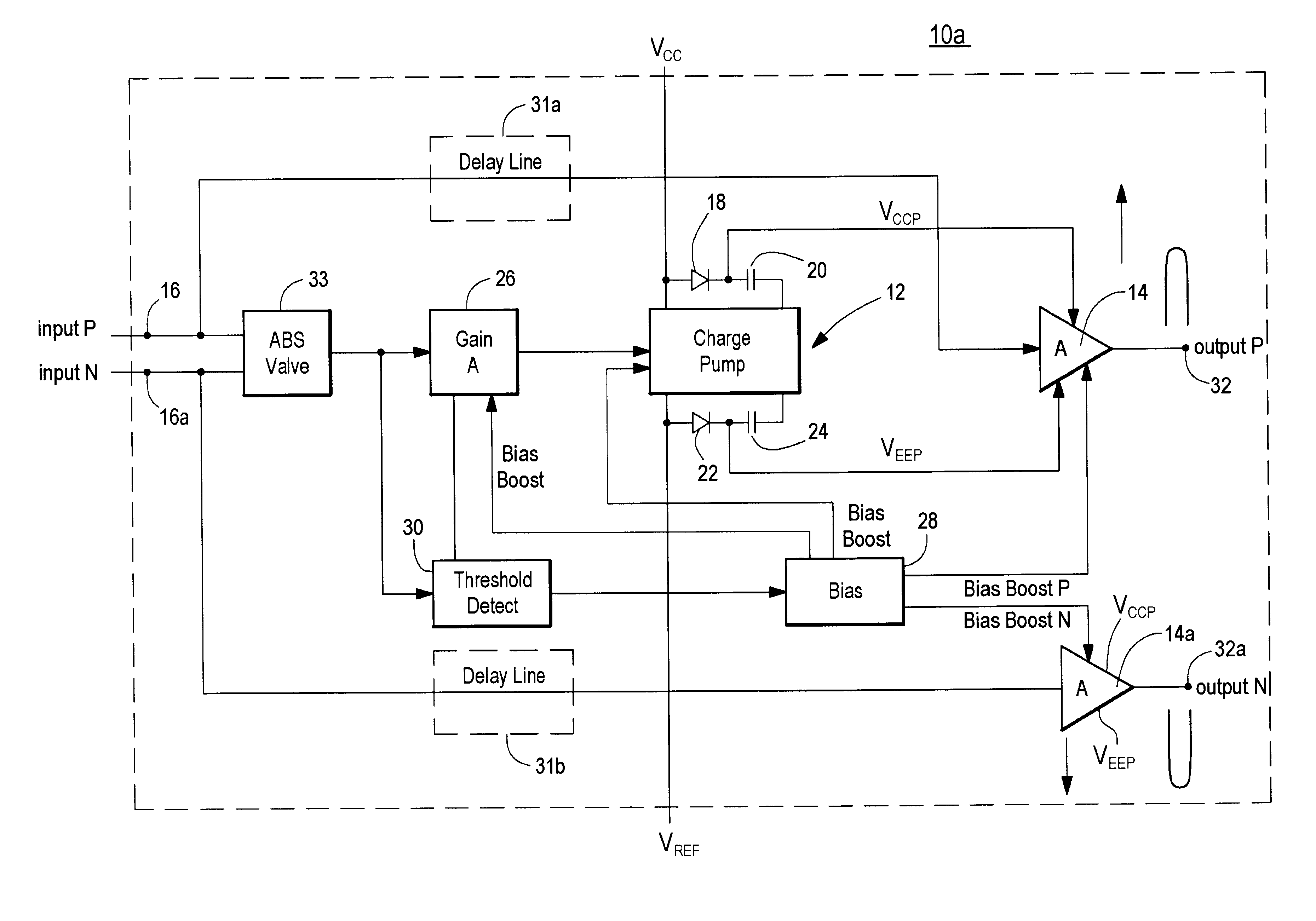
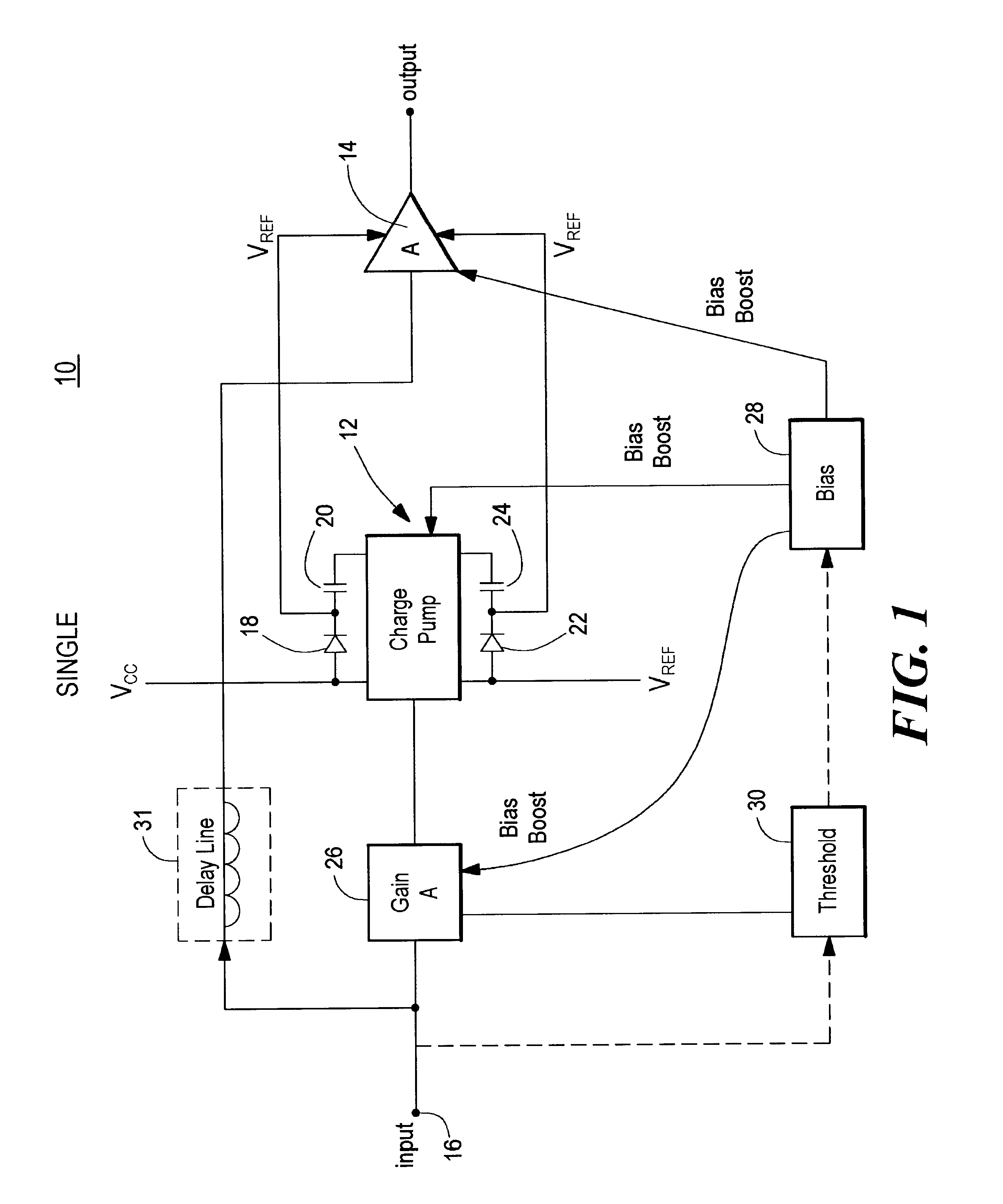
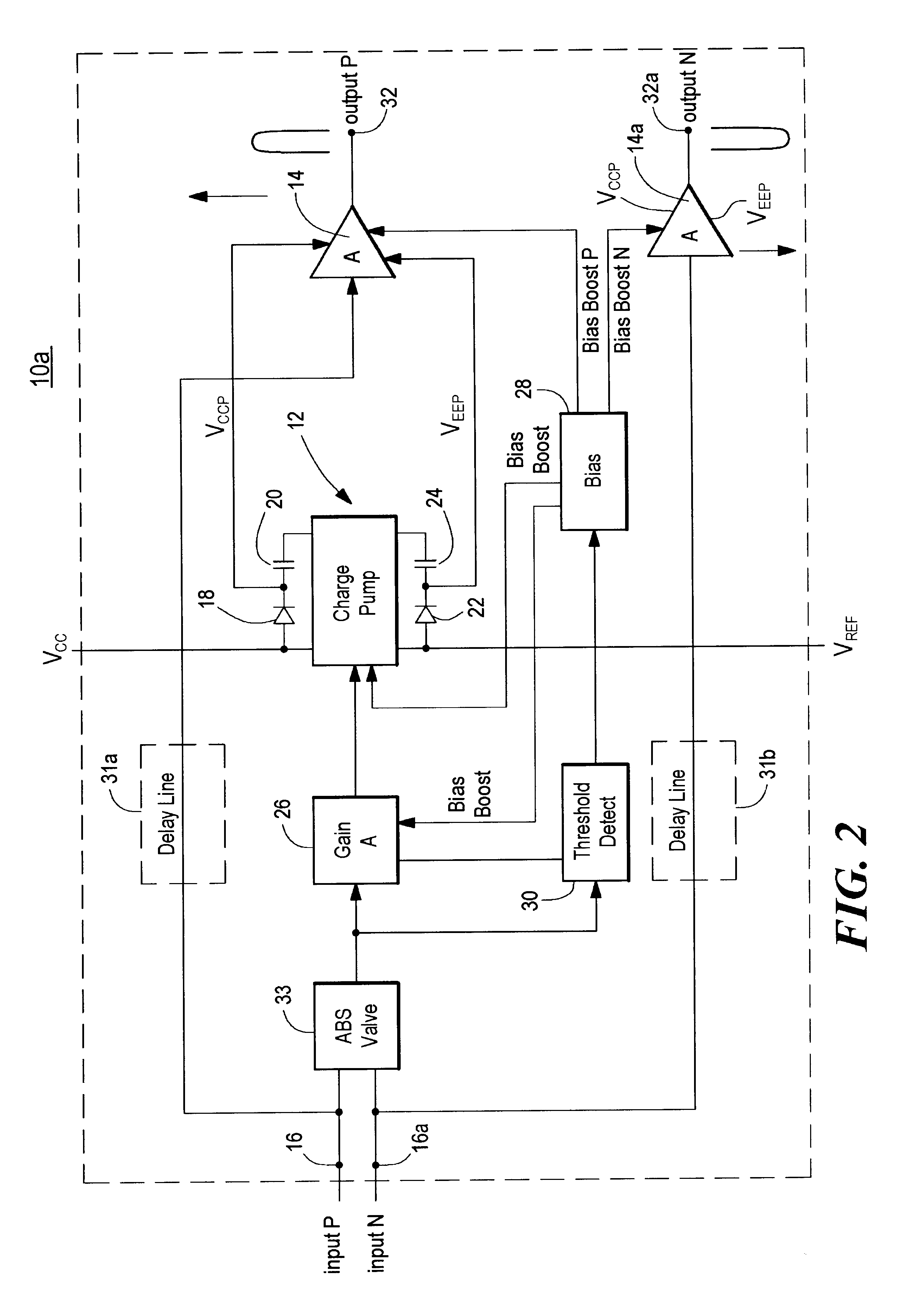
There shown in FIG. 1 an amplifier system with on-demand power supply boost 10 which includes a charge pump 12 and an amplifier 14. The circuit shown in FIG. 1 is a single ended type amplifier. Two power supplies V.sub.CC and V.sub.EE are provided to charge pump 12. V.sub.CC may for example, be +6 volts and V.sub.EE may be -6 volts. A varying input signal is delivered to input terminal 16. Charge pump 12 includes a diode 18 and a charge storage impedance such as capacitor 20 and a diode 22 and capacitor 24. Capacitor 20 charges through diode 18 and capacitor 24 charges through diode 22. As the input signal on terminal 16 fluctuates, the power supply boost V.sub.CCP and V.sub.EEP from capacitors 20 and 24, respectively, are provided to amplifier 14 to assure that there is sufficient power supply voltage to accommodate peak signals when necessary on demand and yet keep the voltage supplied on a low level when the signal is operating in its normal range of RMS voltage. This reduces the...


PUM


Abstract

An amplifier system with on-demand power supply boost includes an amplifier circuit for receiving an input signal and a charge pump connected to positive and negative power supplies and having predetermined supply voltages and being responsive to the input signal for increasing beyond the predetermined supply voltages the supply voltage applied to the amplifier in response to an increase in the input signal and a tracking charge pump usable in the amplifier system which includes a charge storage device; a unidirectional isolation device interconnecting the charge storage device and one pole of a power supply; a driver circuit responsive to an input signal and interconnected between both poles of the power supply; the power supply having predetermined power supply voltages; and a bias circuit for biasing the driver circuit to charge the charge storage device in the charge mode and in the boost mode, for increasing beyond the predetermined power supply voltages, the supply voltage supplied by the storage device to an external load in response to an increase in the input signal.

Description

This invention relates to an improved amplifier system with on-demand power supply boost and to a tracking charge pump useful in such a system.BACKGROUND OF INVENTIONAmplifier efficiency is ratio of power supplied by the amplifier to a load to the power supplied to the amplifier. The crest factor of an applied input signal to an amplifier is the ratio of the peak to RMS levels of that signal. It the crest factor is large enough, the efficiency of the system can be degraded. Further stated: input signals with a generally low RMS value and occasional high peak level cause an amplifier to operate at reduced efficiency. This is so because the power supply is supplying power at a voltage that is at all times sufficient to handle the infrequently occurring peaks and that power is being wasted when the peaks are absent and only the normal RMS levels are present at the input. There are several methods to improve this efficiency. In one approach there are provided a number of power supplies ...

Claims


Application Information

Patent Timeline
Patent Type & Authority Patents(United States)
IPC IPC(8): H03F1/02H02M3/07H03F3/70
CPCH03F1/0222H03F2200/504H03F3/45
Inventor WURCER, SCOTTPIERDOMENICO, JOHN W.
Owner ANALOG DEVICES INC
Why Eureka
Try Eureka