Extendible drain members for grounding RFI/EMI shielding

a drain member and shielding technology, applied in the shield field, can solve the problems of preventing the proper functioning of electronic components, potential problems affecting the safety of vehicles, and preventing electromagnetic interference (emi) and radio frequency interference (rfi), and achieve the effect of convenient grounding

Inactive Publication Date: 2003-10-28
FEDERAL MOGUL SYST PROTECTION GRP INC
View PDF17 Cites 30 Cited by
  • Summary
  • Abstract
  • Description
  • Claims
  • Application Information

AI Technical Summary

Benefits of technology

It is an object of the invention to provide an RFI / EMI shield which is easily groundable.

Problems solved by technology

Electromagnetic interference (EMI) and radio frequency interference (RFI) pose a potential problem preventing the proper functioning of electronic components caused by interference due to inductive coupling between nearby electrical conductors carrying time varying currents or conductors subject to propagating electromagnetic waves.
For example, electrical currents in conductors associated with the ignition system or the electrical power system in an automobile may induce spurious signals in various electronic components, such as an electronic module which controls the functioning of the engine or the braking system.
Such spurious signals could have disastrous consequences and cause the control modules to malfunction or respond as if the spurious induced signals represented a real condition, potentially causing a loss of control of the vehicle.
Similarly, inductive coupling between electrical wiring and the lines carrying data in a computer network or other communication system may have a corrupting effect on the data being transmitted over the network.
While such RFI / EMI sleeving is effective at eliminating electrical interference, the sleeving is difficult to properly ground.
This process is wasteful of sleeving and time consuming for the installer, who must cut more sleeve than needed then cut away some of the sleeve without damaging the drain wire to expose it for connection to ground.

Method used


Image

  • Extendible drain members for grounding RFI/EMI shielding
  • Extendible drain members for grounding RFI/EMI shielding
  • Extendible drain members for grounding RFI/EMI shielding

Examples


embodiment 50

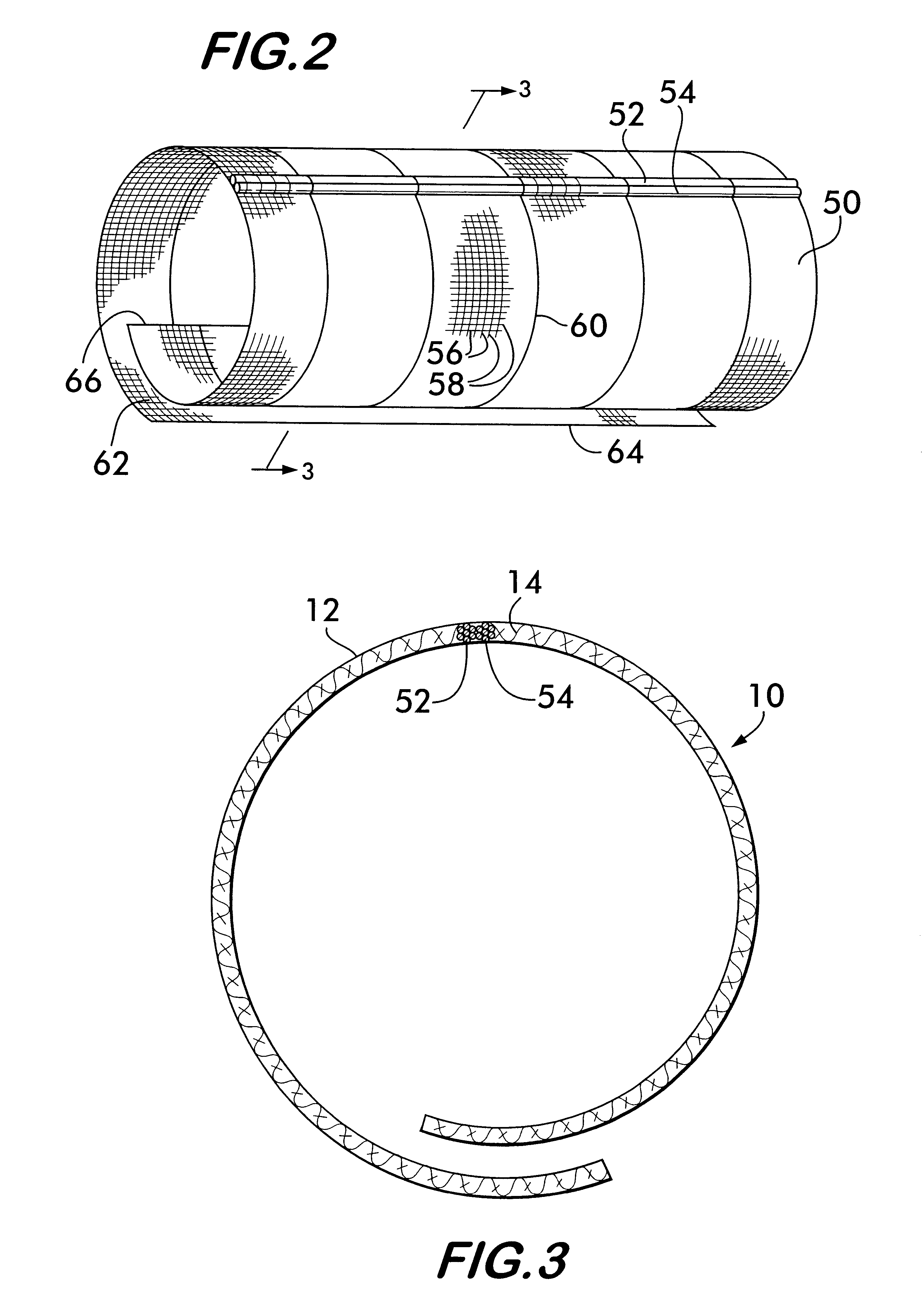
FIG. 2 shows an alternate sleeve embodiment 50 having twin interlaced drain members 52 and 54 according to the invention. Sleeve 50 is preferably of woven construction and comprises both conducting and non-conducting filamentary members 56 and 58 respectively.

Resilient flexible supplementary filamentary members 60 comprised of a material which allows them to be biased or set into a particular shape and resiliently return to that shape are preferably interwoven with filamentary members 56 and 58 to give the sleeve a desired shape and stiffness. The preferred shape is substantially tubular with an open seam 62 arranged lengthwise along the tube and defined by edges 64 and 66 in overlapping relationship. The flexibility of the supplementary filamentary members 60 allows the seam 62 to be temporarily opened by spreading the edges 64 and 66 apart, thereby providing access to the sleeve interior. The resilient bias of the members 60 enables the seam to close with the sleeve edges returnin...

embodiment 86

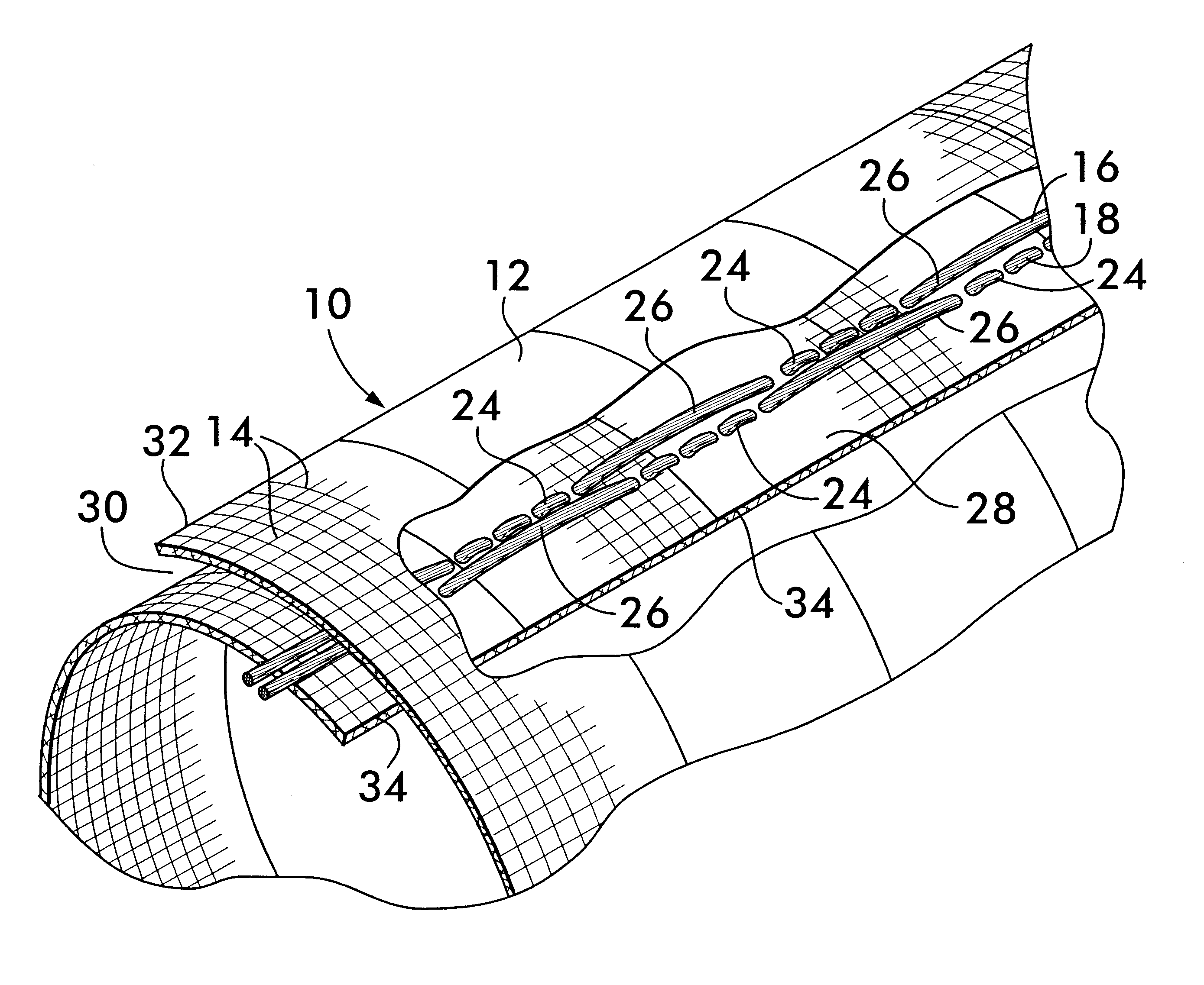
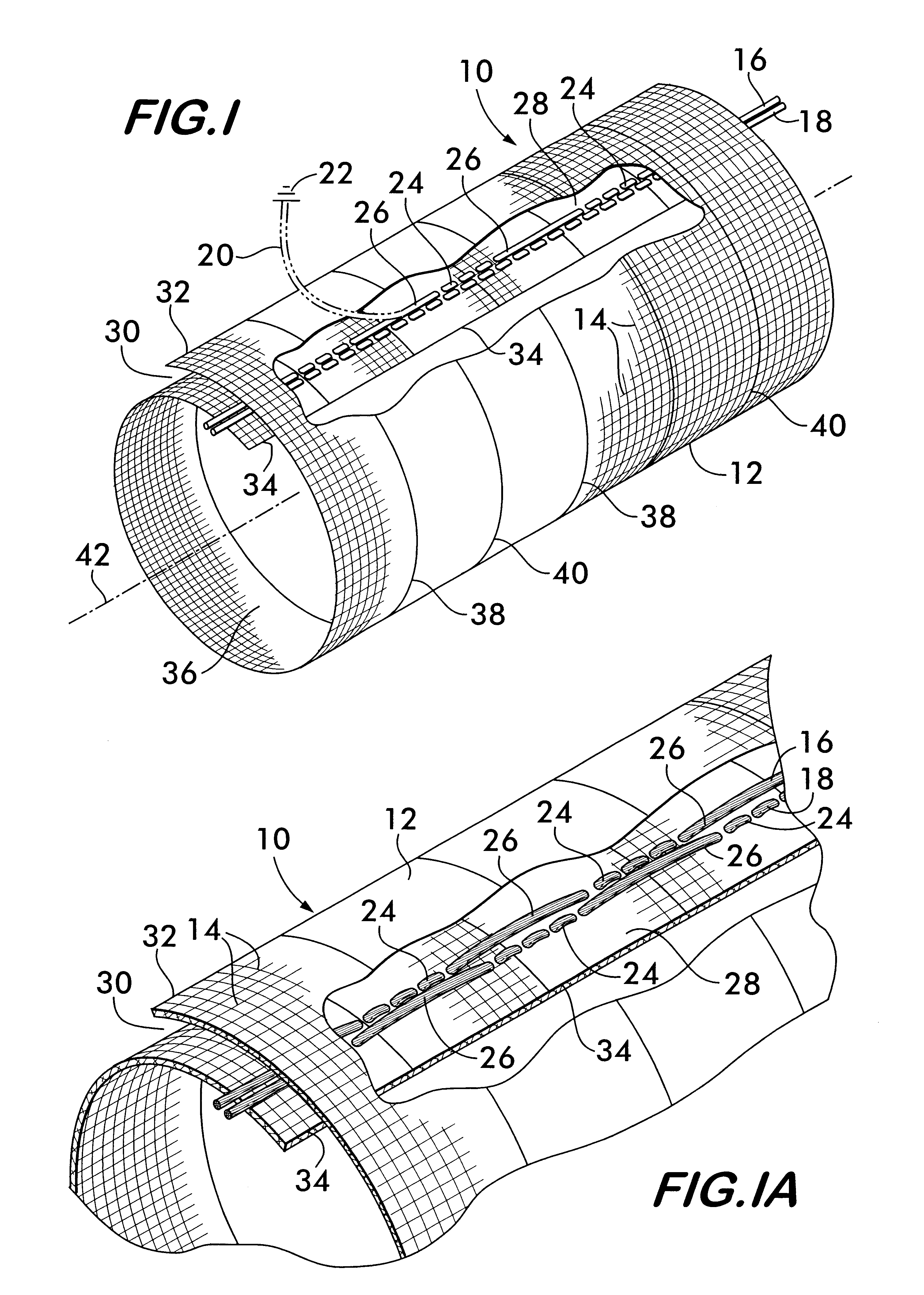
The invention also contemplates use of the twin drain member concept with a sleeve embodiment 86 shown in FIG. 10 not formed of interlaced filamentary members. Non-interlaced sleeve 86 is preferably a laminate comprising a plurality of layers and has at least an outer layer 88 and an inner layer 90 between which drain members 52 and 54 are encased. Preferably, the drain members are confined within a channel 92 which keeps them in contact with one another and the interfacing surfaces 94 and 96 of the inner and outer layers respectively. A conductive coating 98 may be positioned on either of the interfacing surfaces 94 or 96 to provide the RFI / EMI shielding (the coating being shown on the surface 96). The drain members are in contact with coating 98 and are slidable within channel 92 and capable of being drawn outwardly from the channel to effect a ground connection.

The non-interlaced sleeve is preferably made of a resilient, flexible polymer such as polyester, polypropylene and ABS, ...


PUM

PropertyMeasurementUnit
radio frequencyaaaaaaaaaa
flexibleaaaaaaaaaa
resilientaaaaaaaaaa

Abstract

An RFI / EMI shield is formed of interlaced conducting and non-conducting filamentary members. The shield takes the form of a sleeve with a longitudinal seam, the sleeve being biased so that free edges defining the seam are positioned in overlapping relation. A pair of filamentary drain members are positioned adjacent to each other and covered by one of the free edges. One of the drain members is continuously interlaced with the filamentary members forming the sleeve, the other is interlaced at a plurality of attachment regions arranged in spaced relation lengthwise along the sleeve. Between the attachment regions, the drain member floats on the surface of the sleeve and is extendible away from the sleeve for attachment to an electrical ground.

Description

This invention concerns electrically conducting drain members useable to ground sleeves providing shielding from electromagnetic and radio frequency interference.Electromagnetic interference (EMI) and radio frequency interference (RFI) pose a potential problem preventing the proper functioning of electronic components caused by interference due to inductive coupling between nearby electrical conductors carrying time varying currents or conductors subject to propagating electromagnetic waves. For example, electrical currents in conductors associated with the ignition system or the electrical power system in an automobile may induce spurious signals in various electronic components, such as an electronic module which controls the functioning of the engine or the braking system. Such spurious signals could have disastrous consequences and cause the control modules to malfunction or respond as if the spurious induced signals represented a real condition, potentially causing a loss of co...

Claims


Application Information

Patent Timeline
Patent Type & Authority Patents(United States)
IPC IPC(8): H05K9/00H01BH01B11/10H01L25/00
CPCD04C1/06H05K9/0098D03D1/0088D03D1/00H01B11/1091D10B2505/12D10B2403/0311D10B2401/041D10B2403/0112D03D1/0043H05K9/00
Inventor MARKS, PHILIP E.
Owner FEDERAL MOGUL SYST PROTECTION GRP INC
Why Eureka
Try Eureka