Adjustable oscillator

a technology of adjustable oscillator and oscillator, which is applied in the direction of pulse automatic control, modulation, generating/distributing signals, etc., can solve the problems of significant capacitance variation, interference in communication, and inability to implement these frequencies with separate oscillators

Inactive Publication Date: 2003-10-28
III HLDG 3
View PDF2 Cites 38 Cited by
  • Summary
  • Abstract
  • Description
  • Claims
  • Application Information

AI Technical Summary

Benefits of technology

The present invention shows remarkable advantages when compared to solutions of prior art. When the method according to the invention is applied, the control range of the adjustable oscillator can be set to a desired point, wherein for example in communication applications all desired frequencies are attained by means of the oscillator. Tuning according to the invention can also be conducted during the use of the electronic device, and in the tuning it is possible to take into account the possible effects of the temperature on the frequency of the oscillator, wherein the electronic device functions in a more reliable manner. Another advantage attained by means of the invention is that the adjustable oscillator can be implemented in an integrated circuit, wherein the size of the electronic device can be reduced and the manufacturing costs can be decreased. Furthermore, as separate laser tuning is not necessary, the electronic device according to the invention can be manufactured at smaller expenses and within a shorter period of time when compared to a situation where solutions of prior art are used. In that case external measurement devices are not required either.

Problems solved by technology

In electronic devices adjustable oscillators are used especially when two or more different frequencies are required and the implementation of these frequencies with separate oscillators is not reasonable or possible.
In addition, possible frequency variations may cause excess modulation, which causes interferences in the communication.
Thus, problems are caused for instance by the fact that the capacitances of the capacitors used for example in the resonance circuit of the oscillator vary in different integrated circuits, and changes in temperature result in significant variations in the capacitance.
Thus, the frequency control range of the oscillator can shift from the desired one, which complicates the process of producing the correct frequencies in the phase locked loop.
A prior art solution is to adjust the capacitances of the integrated circuit at the manufacturing stage by means of a laser beam, but this method is relatively expensive, and it can be conducted only once, wherein the tuning cannot be performed during the use of the electronic device.
Thus, however, the effect of the disturbances on the signal produced by the oscillator is also increased.
Especially in portable devices in which the aim is to reduce the operating voltage, such solutions would cause the problem that in order to produce the control voltage of the voltage-controlled oscillator, a voltage converter should be used, by means of which higher voltages can be produced from the lower operating voltage.
This, however, increases the power consumption of the electronic device and requires additional components, which is not desirable as the devices become smaller in size and the cost requirements become tighter.

Method used


Image

  • Adjustable oscillator
  • Adjustable oscillator
  • Adjustable oscillator

Examples


Embodiment Construction

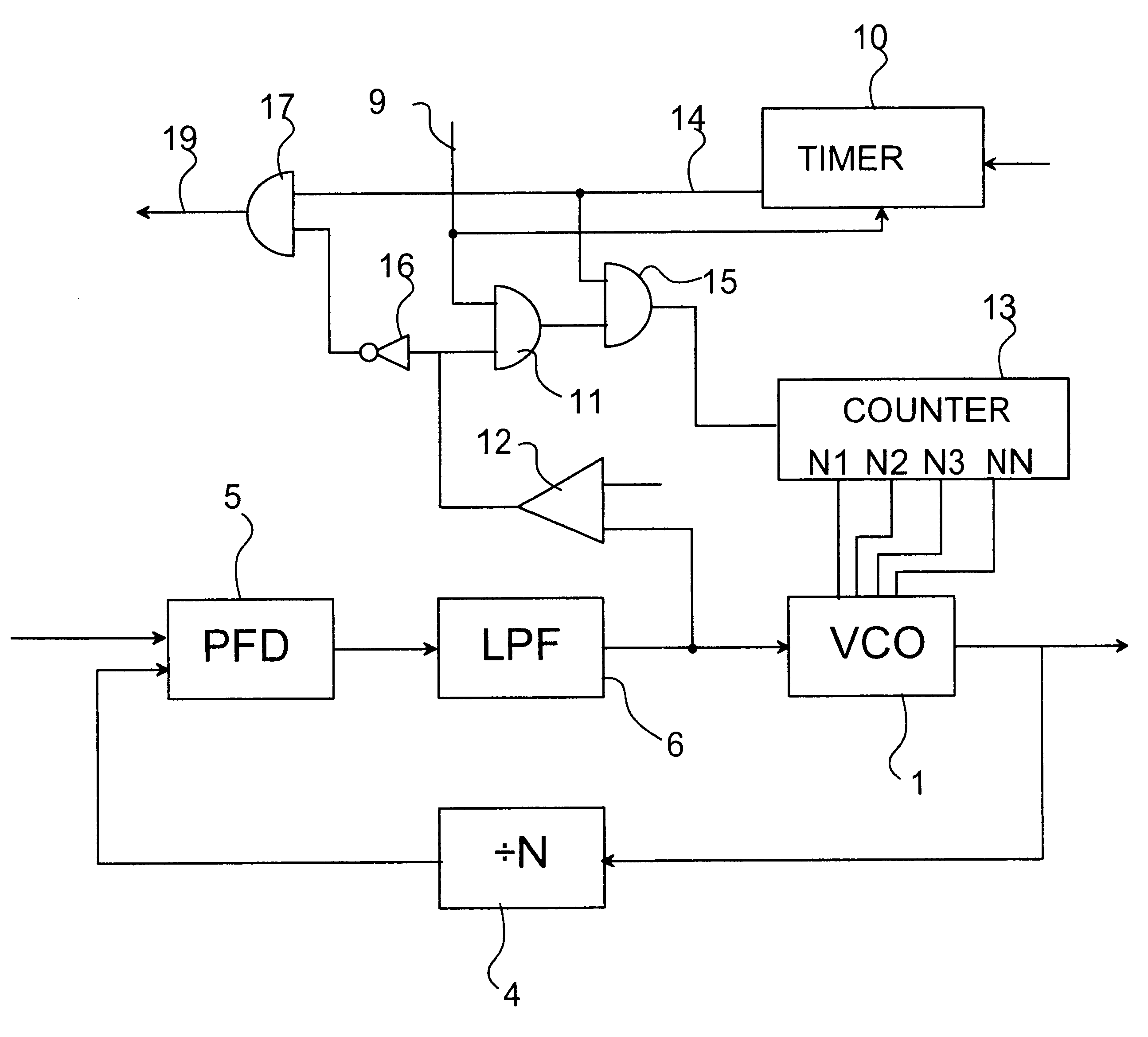
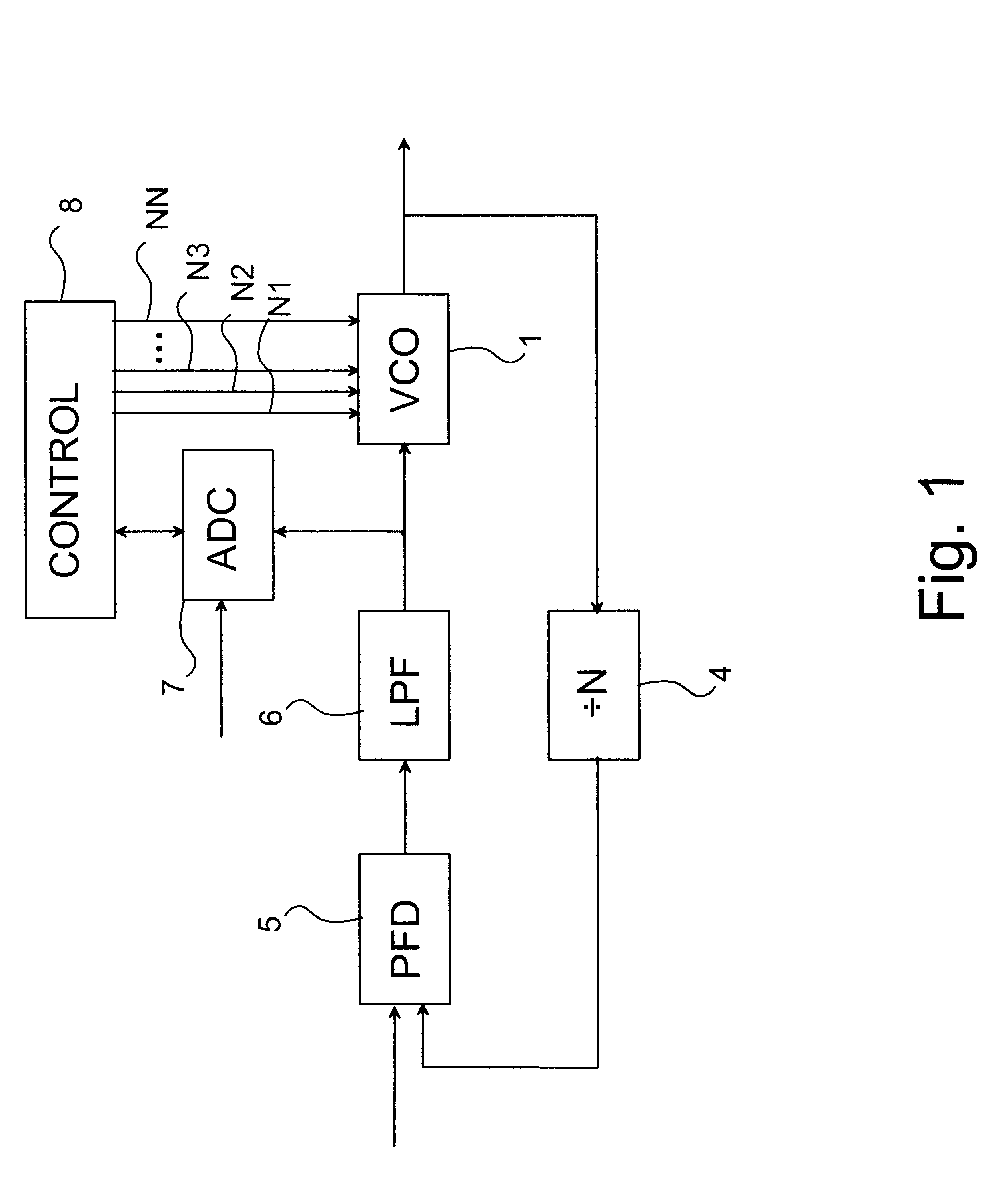
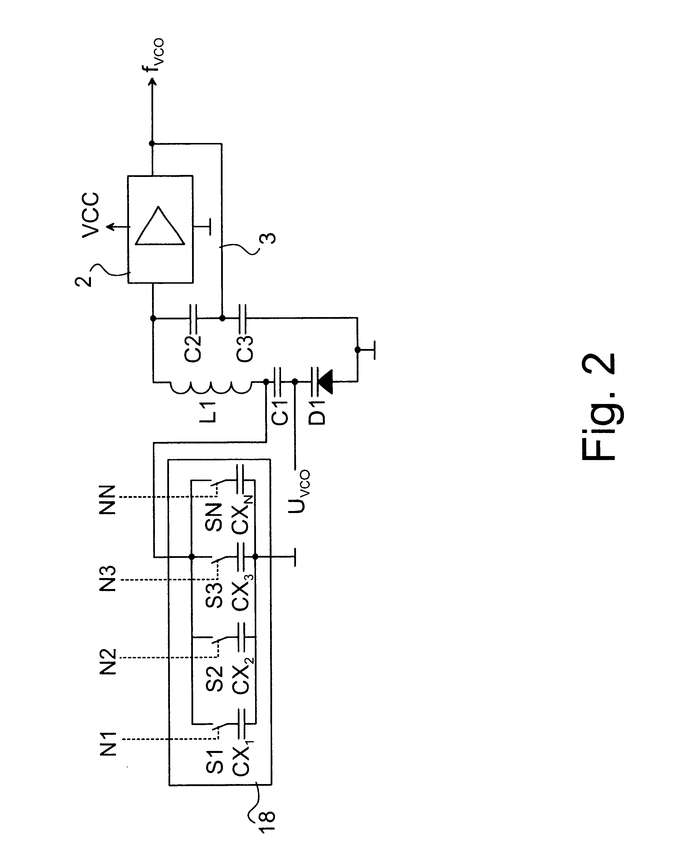
In the following, the invention will be described with reference to FIGS. 1 and 2, using a voltage-controlled oscillator as an example of an adjustable oscillator, but it is obvious that other kind of control method, such as current control, can also be used in connection with the adjustable oscillator 1. In the adjustment of the frequency of the voltage-controlled oscillator 1, for example a voltage-controlled capacitance diode D1 is used. The capacitance of such a capacitance diode D1 is affected by the voltage over the capacitance diode. This capacitance diode D1 is positioned in a frequency control circuit of the adjustable oscillator 1, which forms a resonance circuit. In addition to the capacitance diode D1, the resonance circuit comprises in this preferred embodiment capacitors C1, C2, C3 and a coil L1. The adjustable oscillator also comprises a gain block 2 and a feedback 3 to attain the oscillation of the device. For tuning, the adjustable oscillator is also provided with a...


PUM


Abstract

The invention relates to a method for tuning an adjustable oscillator, in which oscillator at least one resonance circuit is used. The frequency of the oscillator is adjusted by changing the resonance frequency of the at least one resonance circuit by means of a control signal for which a minimum value and a maximum value are selected. In the method at least one target value is selected for the control signal, the frequency of the adjustable oscillator is adjusted to substantially correspond to the target value and the value of the control signal and the target value are compared. When the value of the control signal is substantially different from the target value, a tuning signal is produced to change the resonance frequency of the at least one resonance circuit.

Description

1. Field of the InventionThe present invention relates to adjustable oscillator.2. Brief Description of Related DevelopmentsIn electronic devices adjustable oscillators are used especially when two or more different frequencies are required and the implementation of these frequencies with separate oscillators is not reasonable or possible. Furthermore, adjustable oscillators are used for producing frequencies in a particular frequency range. If the stability of the frequency to be produced is not very significant, it is possible to form such an adjustable oscillator as a voltage-controlled oscillator which has no back coupling. However, in many cases it is necessary to attain certain frequency stability. Thus, the frequency produced by an adjustable oscillator at a given time has to be located in a relatively accurate manner on a desired frequency, and the frequency must not vary significantly. Thus, a feedback loop, such as a phase locked loop (PLL), and an accurate reference frequ...

Claims


Application Information

Patent Timeline
Patent Type & Authority Patents(United States)
IPC IPC(8): H03L7/099H03L7/08H03L7/18H03L7/16G06F1/08H03B1/00H03B5/08
CPCH03L7/18H03L7/099
Inventor ASIKAINEN, KALLESEPPINEN, PAULI
Owner III HLDG 3
Why Eureka
Try Eureka