Power management assembly

a technology of power management and assembly, which is applied in the direction of dc source parallel operation, machines/engines, electric devices, etc., can solve the problems of not addressing the need for complete, effective power management, and too costly to immediately switch or redesign all existing electrical components, etc., to achieve simple terminal insertion connection and easy and quick assembly

Inactive Publication Date: 2003-11-04
YAZAKI NORTH AMERICA
View PDF14 Cites 38 Cited by
  • Summary
  • Abstract
  • Description
  • Claims
  • Application Information

AI Technical Summary

Benefits of technology

A further object of this invention is to join main electrical system elements at a single location in a compact design.
The busboard, batteries, converter and junction box are secured within a power hub case with a lid having doors providing access to the jump start aid posts. The case is compact because of the way the elements fit together, and positions all the elements in a single location. The busboard straightforwardly supports and interfaces with the batteries, power relay and junction box. The provisions of fourteen volt jump aid and forty-two volt jump aid give jump start ability to a vehicle in case of drained batteries, regardless of the type of electrical system in the aiding vehicle. Snap-in interfaces between the busboard plate and cover, simple terminal insertion connection with batteries, and direct interfaces with the junction box provide easy and quick assembly.

Problems solved by technology

Problems have arisen because of the two-to-three kilowatt maximum power limitation of current 14V alternators.
However, it is too costly to immediately switch or redesign all existing electrical components to those that can handle 42V.
These patents do not appear to address the need for complete, effective power management for a dual voltage electrical system.

Method used


Image

  • Power management assembly
  • Power management assembly
  • Power management assembly

Examples


Embodiment Construction

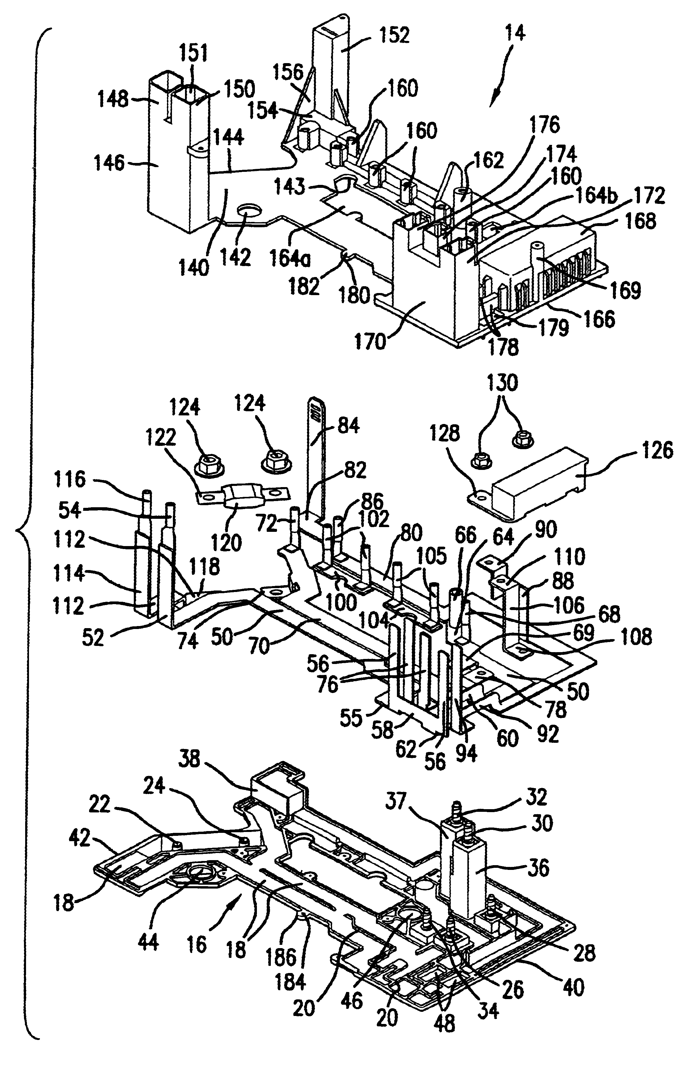
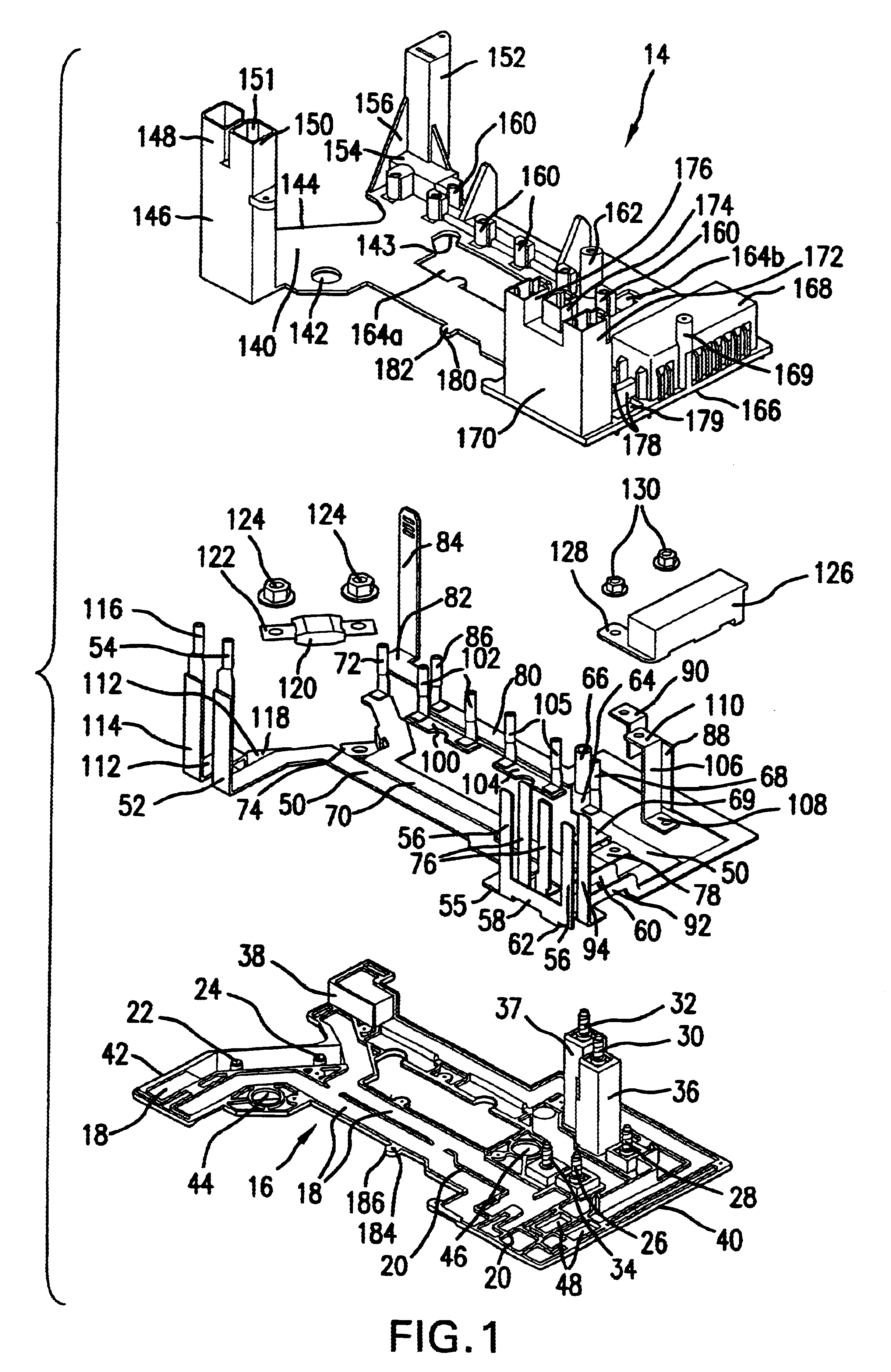
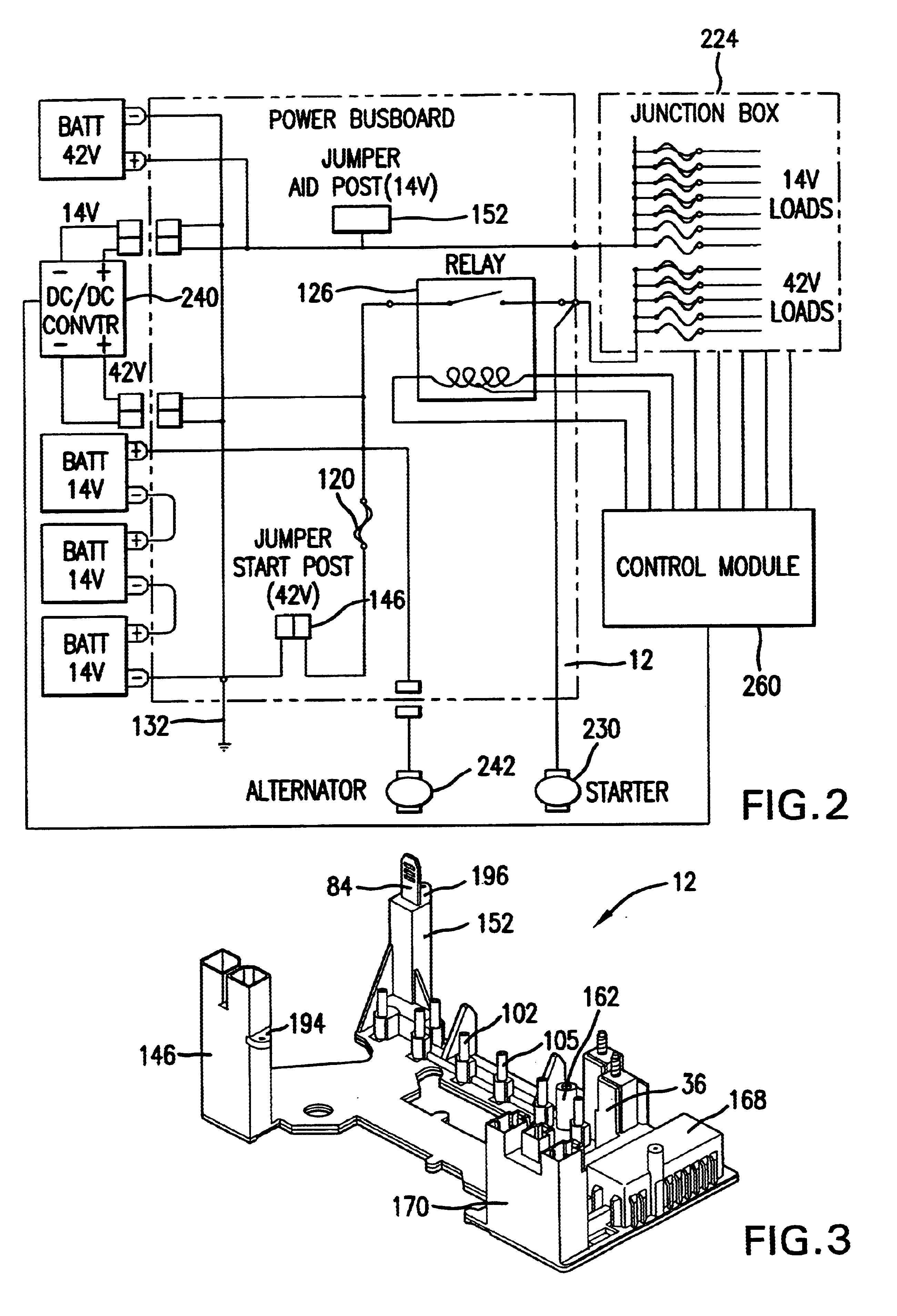
Referring now to FIGS. 1 and 3, a power management busboard 12 according to the present invention has an upper cover 14 and a bottom plate 16 made from an electrically non-conductive material. The plate 16 is molded with multiple recesses 18 for receiving individual busbars that will be sandwiched at least partially if not completely between the lower and upper covers. Adjacent recesses are separated by traces 20 molded between them. Stud bolts 22-34 are secured to the plate in various locations by conventional manner. The bolts may alternatively be injection-molded into the plate. Two adjacent columns 36 and 37 and a short block 38 are formed to extend upward from the plate. The columns 36 and 37 are near a first end 40 of the plate and the block 38 is at an opposite, second end 42. Two of the stud bolts 30 and 32 extend upward from the columns. Spaced apart locating holes 44, 45 and 46 extend through the plate. Openings 48 are for air flow through the plate 16.

The busbars are desi...


PUM

PropertyMeasurementUnit
maximum poweraaaaaaaaaa
voltageaaaaaaaaaa
voltageaaaaaaaaaa

Abstract

A power management system comprises a busboard for selectively managing the power from a forty-two volt source and a fourteen volt source in a vehicle dual voltage electrical system. The busboard has a lower plate with recesses for receiving variously configured busbars. The busbars have upright terminals for electrical connection with the voltage sources. The power from the voltage sources is directed along the busbars to other terminals extending at assorted locations from the busboard. An upper cover fits over the lower plate and covers the recesses. The upper cover has an area accommodating the forty-two volt source and housings for partially enclosing the other terminals. One of the housings forms a forty-two volt jump start post. Another of the housings forms a fourteen volt jump start post. The terminal in the fourteen volt jump start post is connected through a DC / DC converter to the forty-two volt source so power from a vehicle having a fourteen volt electrical system can be converted to forty-two volts and used to charge the dual voltage system. A relay mounted on the busboard is actuated to provide power to a vehicle starter when the batteries are charged. An additional housing provides a connection port for electrically connecting the busboard to a vehicle alternator. Two further terminals on the busboard enable connection of forty-two volt power and fourteen volt power to a junction box requiring each of the separate voltages for serving different sets of electrical components.

Description

1. Field of the InventionThis invention is directed in general to an assembly or arrangement for managing power distribution in a dual voltage electrical system.2. Discussion of Related ArtIn the past, power management in automotive vehicles has been based on fourteen volt (14V) electrical distribution systems. The emergence of new technologies has increased the demand for electrical power. Electrical content of vehicles is steadily growing due to electrical components, such as electric brakes and steering, performing the functions of previously mechanical components, and due to the addition of information and entertainment networks. Problems have arisen because of the two-to-three kilowatt maximum power limitation of current 14V alternators. Within the industry, proposals have been made to increase the electrical system voltage to forty-two volts (42V). In this way, higher power output can be obtained from the alternator without dramatically increasing the output current. However, ...

Claims


Application Information

Patent Timeline
Patent Type & Authority Patents(United States)
IPC IPC(8): H01B11/02H01M2/10H01M2/36H01R9/22
CPCH01M2/1083H01R9/226H01M2/362Y02E60/10
Inventor YANG, SHENGHUA
Owner YAZAKI NORTH AMERICA
Why Eureka
Try Eureka