Seed sowing apparatus

a technology of seed sowing apparatus and sown seed, which is applied in the direction of seeding apparatus, fertiliser and seeding device, spades, etc. it can solve the problems of reducing the separation distance and geometry between the two products sown, the edge no longer functions to deflect material to the outer periphery of the disc, and the effect of improving the contact and traction of the disc and the soil

Inactive Publication Date: 2003-11-11
BAKER CHRISTOPHER JOHN
View PDF6 Cites 12 Cited by
  • Summary
  • Abstract
  • Description
  • Claims
  • Application Information

AI Technical Summary

Benefits of technology

In view of severe abrasive conditions to which the blade is subjected, the blade should preferably be cast from wear resistant steel or other abrasion-resistant material. Since the design allows for a reduction in metal requirements, compared to conventional blades, a saving in cost of relatively expensive wear resistant steel material also be achieved. Other materials, for example, ceramics, tungsten carbide, or similar materials or a combination of materials may also be used in constructing the blade.
Because the blade is preferably slipped into its pivotal connection to in the stationary mounting component from the rear edge of the blade, and the recess discussed above is preferable in the front portion of the blade, the overlap provided by the recess and protrusion is only effective when a blade is pushed fully into its mount. Minimal clearance between these components is desirable to prevent ingress of straw and other debris and to allow for casting inaccuracies.

Problems solved by technology

This is an important feature since contact between these two materials in the soil often results in the fertiliser having a toxic effect on the seed.
These types of devices in their present form have several problems:
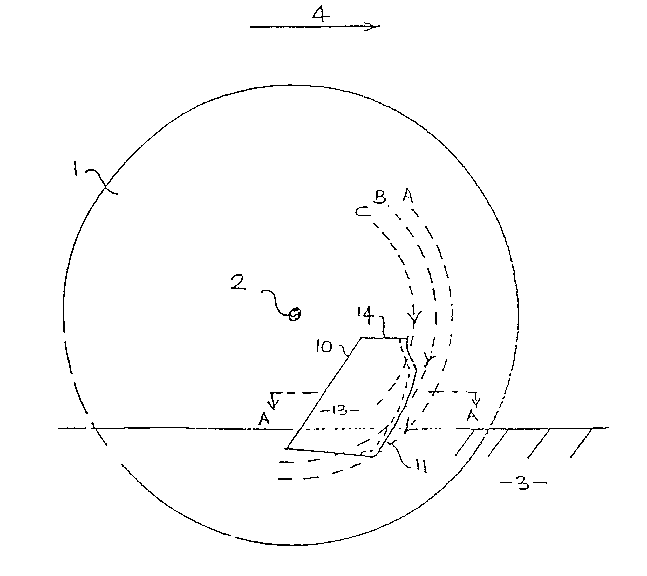
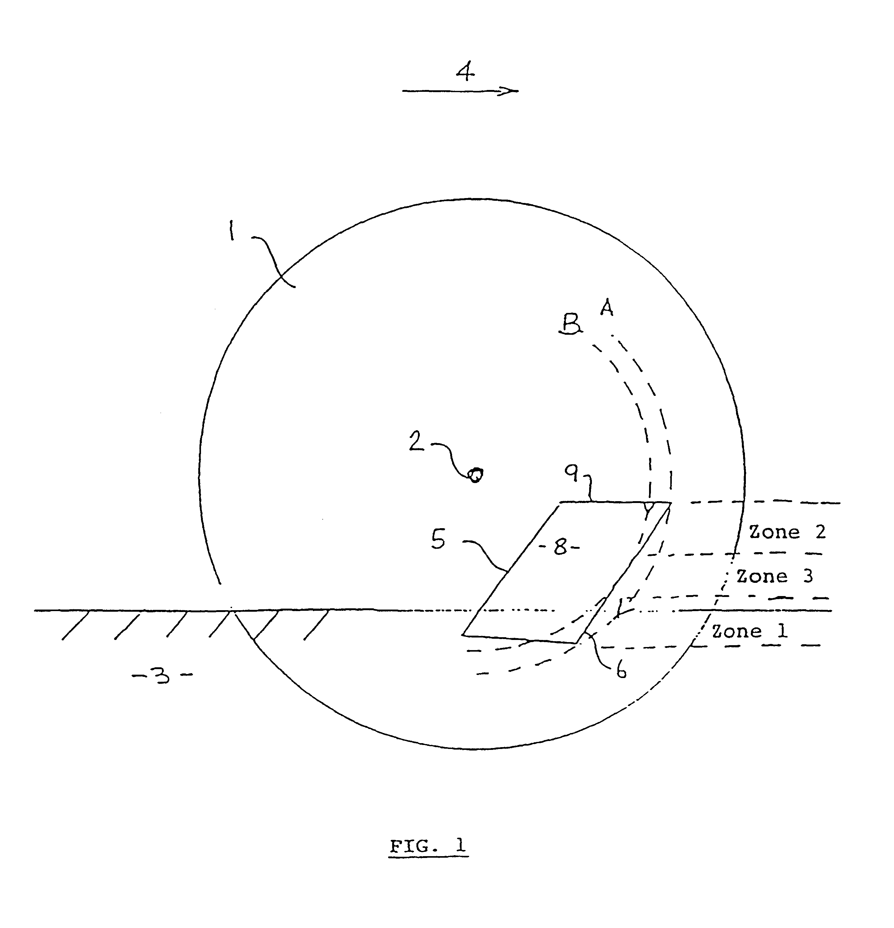
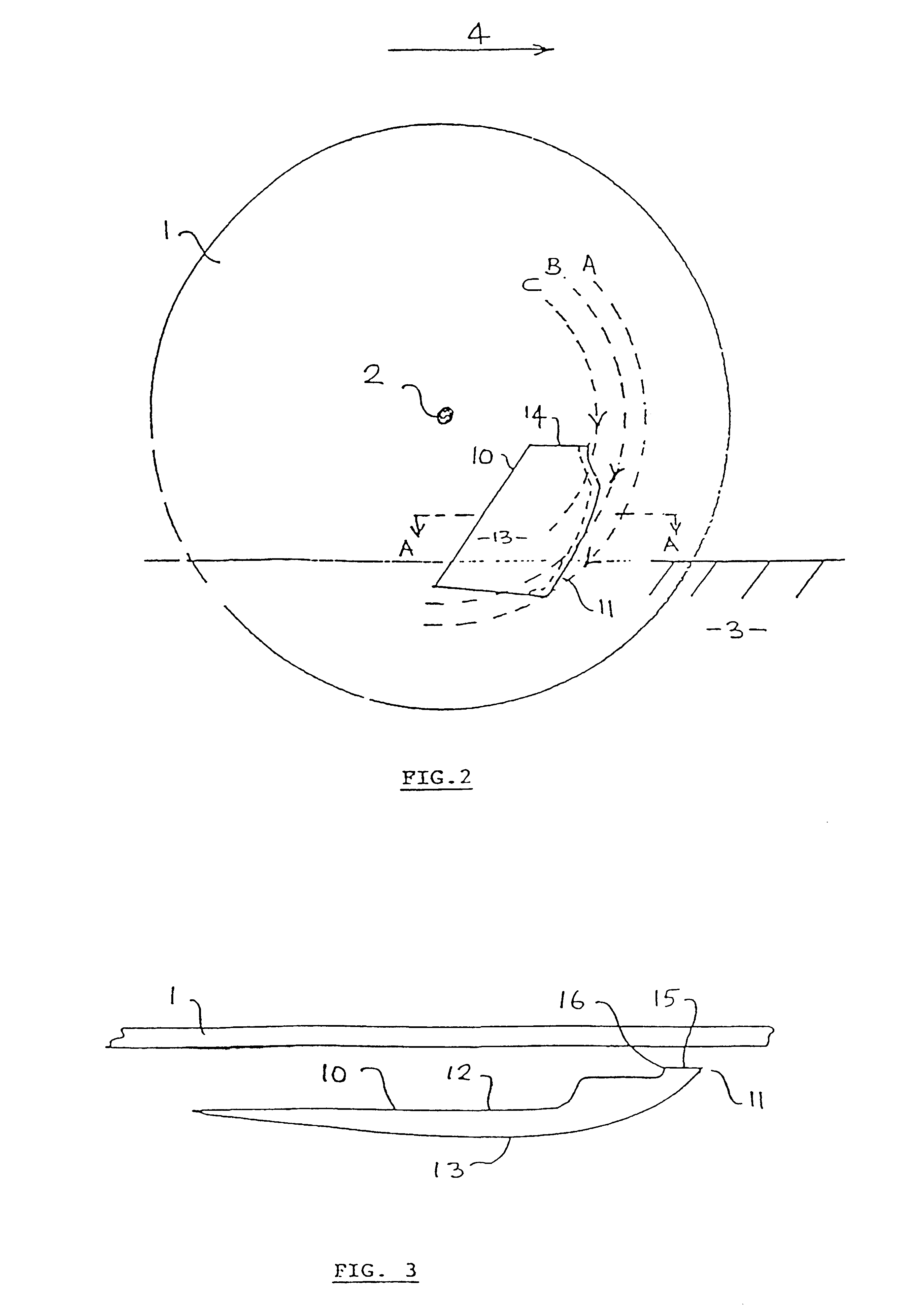
However, inevitably, due to design requirements, at an upper portion of the leading edge (referred to herein as zone 2), the angle with respect to the arc becomes negative, and the leading edge no longer functions to deflect material to the outer periphery of the disc.
Although this may not be a problem with dry soils where minimal soil, roots or plant residue material adheres to the disc, this can be a problem in wet and / or sticky soils.
The problem in wet or sticky soils is that a thin film of soil and plant material often adheres to the disc surface and is wiped off by the inside surface of the blade in the negative angle zone 2 region.
This causes a build-up of unwanted soil to occur between the inner blade surface behind the leading edge, and the disc.
As this build-up is cumulative, it eventually forces the blade to lose contact with the disc, which largely destroys the ability of the blade (and thus the whole device) to clear plant residues.
Since the ability to clear such residues is an essential ingredient in its intended function, this problem interferes with the function of the device in the field.
This window has proven to be only partially successful in practice, since it is limited in size by the physical dimensions of the blade, and often the window itself becomes blocked with soil, thus negating its function altogether.
A further problem arises because each blade is pivotally mounted at its top about a substantially horizontal-longitudinal axis to allow the blade to deflect a limited amount laterally so that it can maintain faithful contact with the disc as the latter flexes naturally in response to the heterogeneity of the soil and the changing direction of travel.
When this occurs the scraping function in the positive angle zone 3 and zone 1 regions is compromised, allowing straw and / or other material and residue on the blade to ingress so that eventually the residue-clearance ability of the device fails, and an undesirable field blockage occurs which seriously disrupts the seeding function unless cleared.
At best, clearance of the blockage represents a field stoppage, costing downtime and the loss of operating efficiency.
However, as such a side blade is of necessity reasonably short, it has been found to be only effective when used in combination with a disc that does not travel straight ahead.
Were it not for the angling of the disc, residue would collect in the region of the supporting bracket, which leads to problems with the operation of the side blade (such as those described above).
An additional problem with existing seed sowing devices arises because of the need to form an intimate contact between a new blade and the disc surface.
Where such intimate contact is not quickly established for a new blade, a thin film of soil may flow between portions of the blade's leading edge and the disc, which erodes the inner face of the blade's leading edge, causing it to become rounded inwards.
This interferes with the function of the whole device by separating a blade from the disc.
However, the action of the wings in creating the soil shelves results in lateral braking forces being applied by the soil against the blades and hence by the blades against the disc.
In some circumstances the frictional braking forces of the blades upon the disc may become excessive when the soil is of a plastic nature.
Some of these soils also have little inherent shear strength and offer relatively poor traction to the disc--with the result that the disc may slip or stop turning altogether.
This adversely affects the ability of the whole device to handle surface residues without blockage and / or to deposit seed and fertiliser in the soil in a regular pattern.
The variability of draw-in forces at shallow operating depths makes the setting of accurate depths difficult, which adversely affects germination of the seeds being sown and the emergence of their seedlings.
A further problem with the above designs occurs when, in some applications it is desirable to apply the fertiliser as a liquid or to apply a liquid innoculant or liquid pesticides.
A further problem with the above designs is caused by the pivotal linkage of a blade to a stationary mounting component.
This clearance sometimes allows straw and other material to enter the seed or fertiliser channel located immediately behind it in the blade, which can, over time, cause the seed or fertiliser channel to become blocked.
This results in uneven wear on the inside surfaces of the blades through continuous contact with the disc.
This creates "high-spots" on the less-worn portions of the blades which in turn raise the rest of the blades fractionally off the disc surface and allow straw or other plant residues to jam between the blades and the disc, causing blockage and lifting the blade off the disc.
In some circumstances when the soil is hard and dry, penetration of the disc is difficult because of the cemented nature of the soil.

Method used


Image

  • Seed sowing apparatus
  • Seed sowing apparatus
  • Seed sowing apparatus

Examples


Embodiment Construction

Aspects of the present invention have been described by way of example only and it should be appreciated that modifications and additions may be made thereto without departing from the scope thereof as defined in the appended claims.

A conventional seed sowing apparatus to which the present invention is addressed is shown schematically in FIG. 1. The seed sowing apparatus comprises a flat circular disc 1 mounted on a frame so as to be rotatable about a horizontal axle 2 while partly embedded in soil 3 and drawn in a forward direction generally indicated by arrow 4 substantially parallel to the surface of the soil 3 and perpendicular to the axle 2. A blade 5 of the seed sowing apparatus includes a leading edge 6 defined by the intersection of an inner face or side surface 7 (not visible in the figure) facing the surface of the disc 1 and an outer face or side surface 8. The outer face 8 is formed as a substantially curved surface in section view such that the surface in the region of ...


PUM


Abstract

The present invention relates to a seed sowing apparatus which includes a substantially flat circular disc (1) mounted on a frame so as to be rotatable about horizontal axis (2) while partly embedded in soil (3) and drawn in a forward direction substantially parallel to the soil surface and substantially perpendicular to a disc axle. The apparatus also includes at least one blade (10) having a leading edge (11) defined by the intersection of two opposite side surfaces and structure (41, 45) for mounting the blades on the apparatus so that the leading edge (11) is held close to or in intimate contact with the disc (1), wherein the at least one blade's leading edge (11) is inclined in a plane of the blade such that an angle of the leading edge (11) with respect to an arc (A, B, C) of the disc surface passing beneath the leading edge (11) is zero or positive over the entire length of the leading edge (11).

Description

This invention relates to improvements to the blades of a seed sowing apparatus, which has also previously been referred to as a ground channelling apparatus.Apparatus for sowing seeds into untilled soils (usually covered by plant residues) wherein the seed is deposited into a slit formed in the ground by a disc have been generally described in the following patents."Improvements in and relating to seed sowing implements"--New Zealand No. 184742, U.S. Pat. No. 4,275,671, Canada No. 1092899, United Kingdom No. 2001513, France No. 79 / 01024, and Australia No. 517689,"Seed sowing apparatus"--New Zealand No.237288, U.S. Pat. No. 5,269,237, Canada No. 2062 / 60-5, EU (France, United Kingdom, Spain, Germany) No. 92301760.2, Australia No. 662121, Norway No. 92.0820, Japan No. 4-80523, South Africa No. 92 / 1553.Amongst the novel features of the designs described in the above patents, are one or more winged side blades which are arranged so that they each contact the lateral faces on either side...

Claims


Application Information

Patent Timeline
Patent Type & Authority Patents(United States)
IPC IPC(8): A01C5/00A01C5/06A01C7/06A01C7/00A01B15/16A01B49/06A01C7/20
CPCA01C7/06A01C5/064
Inventor BAKERKERNOHAN, CRAIG DAVIDROBINSON, DAVID JOHNRITCHIE, WILLIAM ROWLAN
Owner BAKER CHRISTOPHER JOHN
Why Eureka
Try Eureka