Co-based magnetic alloy and magnetic members made of the same

a technology of co-based magnetic alloys and magnetic members, which is applied in the direction of magnetic materials, basic electric elements, magnetic bodies, etc., can solve the problems of large noise generation, deterioration of magnetic properties under stress, and unsuitability of ferrite materials for high-power applications

Inactive Publication Date: 2003-11-18
HITACHI METALS LTD
View PDF2 Cites 45 Cited by
  • Summary
  • Abstract
  • Description
  • Claims
  • Application Information

AI Technical Summary

Problems solved by technology

The ferrite materials are unsuitable for high power applications in a high frequency range in which an operating magnetic flux density increases and a temperature rises, because the ferrite materials exhibit low saturation magnetic flux density and inferior temperature characteristics.
Because of large magnetostriction, Fe-base amorphous alloys have problems that magnetic properties are deteriorated under stress and that a large noise is generated in a use, wherein, for example, currents of an audio-frequency range are superimposed.
On the other hand, a Co-base amorphous alloy is thermally unstable.
Therefore, if the Co-base amorphous alloy, which exhibits good properties for high-frequency applications, is used in applications which requires a high power, there will arise a problem that high-frequency magnetic properties are deteriorated because a large property change against time occurs.
However, an optimum operating frequency range for use in the transformer is around several tens of kilohertz for thin strip materials, and the properties are not sufficient for applications in the high frequency.
In these uses, a high-permeability material having a relative magnetic permeability of several tens of thousands in a low-frequency region has a problem that the magnetic core material is magnetically saturated and that a sufficient property cannot be obtained in the high frequency range.
However, the granular thin film with high electric resistance has a limitation in increasing a volume of the magnetic material, and it is difficult to use the thin film as the magnetic core material for a magnetic switch, transformer, choke coil, and so on in a pulse power applications handling a high energy and a large-capacity inverter.
However, a sufficiently high Q cannot be obtained in a megahertz (MHz) or higher range, even when the alloy is heat-treated in a magnetic field and a magnetic anisotropy is induced in the alloy.
Moreover, there are problems of a magnetic saturation of the material by superimposed direct-current or by an unbalanced signal, when the material is used in the choke coil for a three-phase power line.
However, the disclosed alloy contains a large amount of borides.
There are problems that even with the heat treatment in the magnetic field, a high Q in the high frequency range, and a sufficiently low squareness ratio, or a sufficiently high squareness ratio cannot be obtained.
On the other hand, when the heat treatment is performed without magnetic field, that is, when the heat treatment in the magnetic field is not applied, the high-frequency magnetic property is deteriorated.
Moreover, when the magnetic field sufficient for saturating the alloy is applied in generally the same direction as the magnetization direction during use and the heat treatment is performed, and when a is 0.35 or more, the squareness ratio is liable to drop unfavorably.
When y is less than 1.5 atomic %, a fine crystal grain structure is not obtained after the heat treatment, and unfavorably a high Q is not obtained.
When y exceeds 15 atomic %, the temperature property is disadvantageously deteriorated.
When c exceeds 30 atomic %, the saturation magnetic flux density disadvantageously decreases.

Method used


Image

  • Co-based magnetic alloy and magnetic members made of the same
  • Co-based magnetic alloy and magnetic members made of the same
  • Co-based magnetic alloy and magnetic members made of the same

Examples


example 2

A molten alloy having a composition represented by the general formula (Co.sub.1-a Fe.sub.a).sub.bal. Cu.sub.0.6 Nb.sub.2.6 Si.sub.9 B.sub.9 (atomic %) was quenched in the single roll method to obtain a thin amorphous alloy strip having a width of 5 mm and thickness of 18 .mu.m. The thin amorphous alloy strip was wound into a toroidal magnetic core with an outer diameter of 19 mm and an inner diameter of 15 mm.

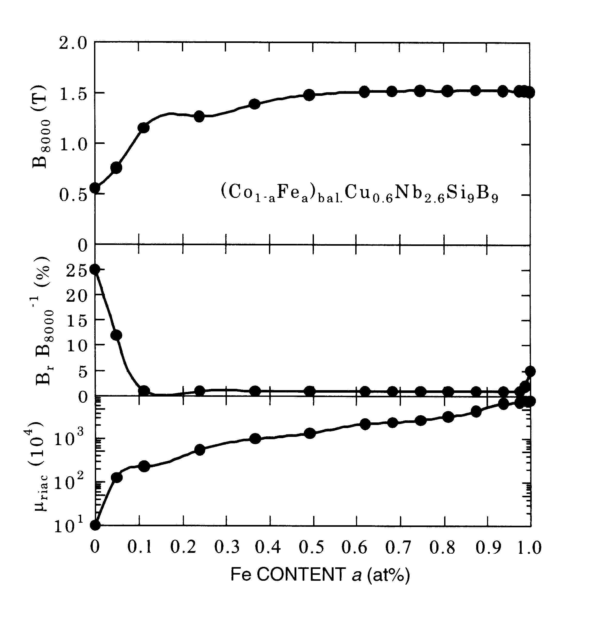
The magnetic alloy core was annealed in accordance with the same heat treatment pattern as that in Example 1, and magnetic properties of the core were measured. The heat-treated alloy were formed fine crystal grains having a grain size of not more than 50 nm. FIG. 4 shows Fe content (a) dependence of a saturation magnetic flux density B.sub.s, squareness ratio B.sub.r / B.sub.8000, and alternating-current relative initial permeability .mu..sub.riac at 1 kHz. FIG. 5 shows a dependence of an induced magnetic anisotropy constant K.sub.u on the Fe content (a). And FIG. 6 shows Fe c...

example 3

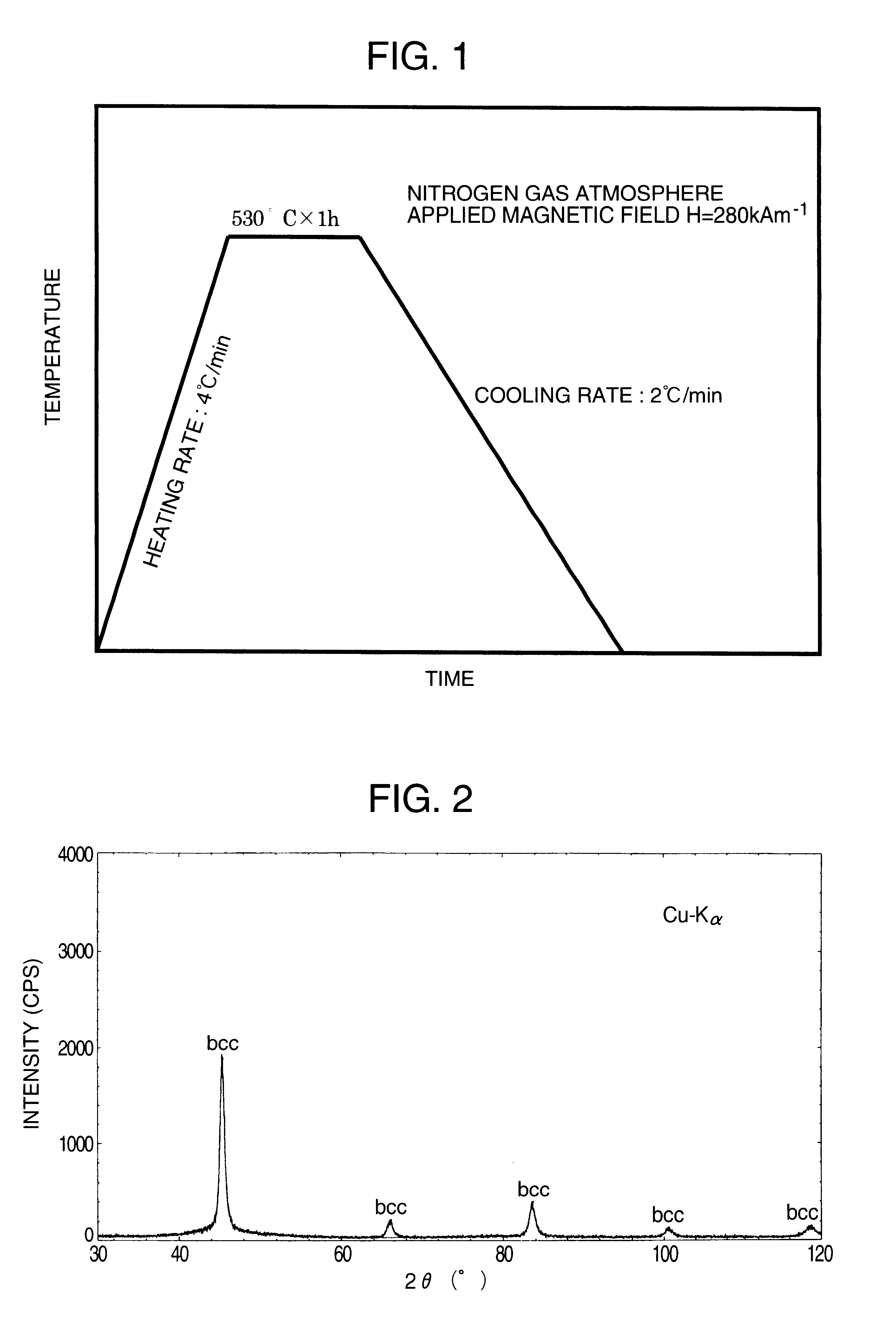
Molten alloys each having a chemical composition shown in Table 2 were rapidly quenched by the single roll method under the atmosphere or an Ar gas atmosphere to obtain thin amorphous alloy strips each having a width of 10 mm and thickness of 15 .mu.m. The alloys containing active metals such as Zr, Hf were fabricated under an Ar gas atmosphere. The thin amorphous alloy strips were wound into troidal magnetic cores having an outer diameter of 19 mm and an inner diameter of 15 mm. The magnetic alloy cores were subjected to heat treatment in accordance with the heat treatment pattern shown in FIG. 1. During the heat treatment, the magnetic field was applied in the direction perpendicular to the magnetic path of the magnetic core (in the width direction of the thin alloy strip). In the heat-treated alloys, there were formed extremely fine crystal grains having a grain size of not more than 50 nm and having a bcc phase, fcc phase, or hcp phase, respectively. With regard to the heat-trea...

example 4

A molten alloy of (Co.sub.0.8 Fe.sub.0.2).sub.bal. Cu.sub.1 Nb.sub.3 Si.sub.13.5 B.sub.9 (atomic %) was rapidly quenched in the single roll method to obtain a thin amorphous alloy strip having a width of 25 mm and thickness of 18 .mu.m. The thin amorphous alloy strip was wound into troidal magnetic cores having an outer diameter of 25 mm and an inner diameter of 20 mm. The magnetic field was applied in the height direction of the magnetic core (in the width direction of the thin alloy strip) and the magnetic alloy core was subjected to heat treatment in a magnetic field. The heat treatment was performed in accordance with the same heat-treatment pattern as that of Example 1, while the magnetic field was applied to the core through the period. It was confirmed by a transmission electron microscope and X-ray diffraction that there was formed crystal grains in the alloy, which have a grain size of 10 to 20 mm and body-centered cubic structure. According to a result of measurement of th...


PUM

PropertyMeasurementUnit
grain sizeaaaaaaaaaa
particle sizeaaaaaaaaaa
temperatureaaaaaaaaaa

Abstract

Disclosed is a Co-base magnetic alloy excellent in high-frequency magnetic properties, of which chemical composition is represented by the following general formula, by atomic %, (Co1-aFea)100-y-cM'yX'c, where M' is at least one element selected from the group consisting of V, Ti, Zr, Nb, Mo, Hf, Sc, Ta and W; X' is at least one element selected from the group consisting of Si and B; and a, y and c are defined by the formulas of a<0.35, 1.5<=y<=15, and 4<=c<=30, respectively. At least a part of the alloy structure of the alloy consists of crystal grains having an average grain size of not more than 50 nm. The alloy has a relative initial permeability of not more than 2000. It is suitably used for members of countermeasure against noise such as zero phase reactors for large current and electromagnetic shielding materials, inverter transformers, choke coils for active filters, antennas, smoothing choke coils, power supplies for lasers, pulse power magnetic members for accelerators.

Description

1. Field of the InventionThe present invention relates to a Co-base magnetic alloy having excellent high-frequency magnetic properties, which is used in members of countermeasure against noise such as zero phase reactors and electro-magnetic shielding materials, inverter transformers, choke coils for active filters, antennas, smoothing choke coils, saturable reactors, power supplies for laser, pulse power magnetic members for accelerators, and so on. It also relates to high performance magnetic members made of the Co-base magnetic alloy.2. Description of the Prior ArtFerrite, amorphous alloys, nano-granular thin film materials, and so on have been known as magnetic materials for high frequency applications. The ferrite materials are unsuitable for high power applications in a high frequency range in which an operating magnetic flux density increases and a temperature rises, because the ferrite materials exhibit low saturation magnetic flux density and inferior temperature characteri...

Claims


Application Information

Patent Timeline
Patent Type & Authority Patents(United States)
IPC IPC(8): C22C45/00C22C45/04H01F1/153H01F1/12
CPCC22C45/04H01F1/15333H01F1/15316
Inventor YOSHIZAWA, YOSHIHITO
Owner HITACHI METALS LTD
Why Eureka
Try Eureka