
Actuator retract circuit for dual speed hard disk drive

a technology of actuator and retract circuit, which is applied in the direction of magnetic recording, magnetic recording, instruments, etc., can solve the problems of reducing data access time, battery power depletion, and active rectifiers, which have the highest efficiency, and are significantly more complex

Inactive Publication Date: 2003-11-18
HITACHI GLOBAL STORAGE TECH NETHERLANDS BV
View PDF6 Cites 3 Cited by
  • Summary
  • Abstract
  • Description
  • Claims
  • Application Information

AI Technical Summary

Benefits of technology

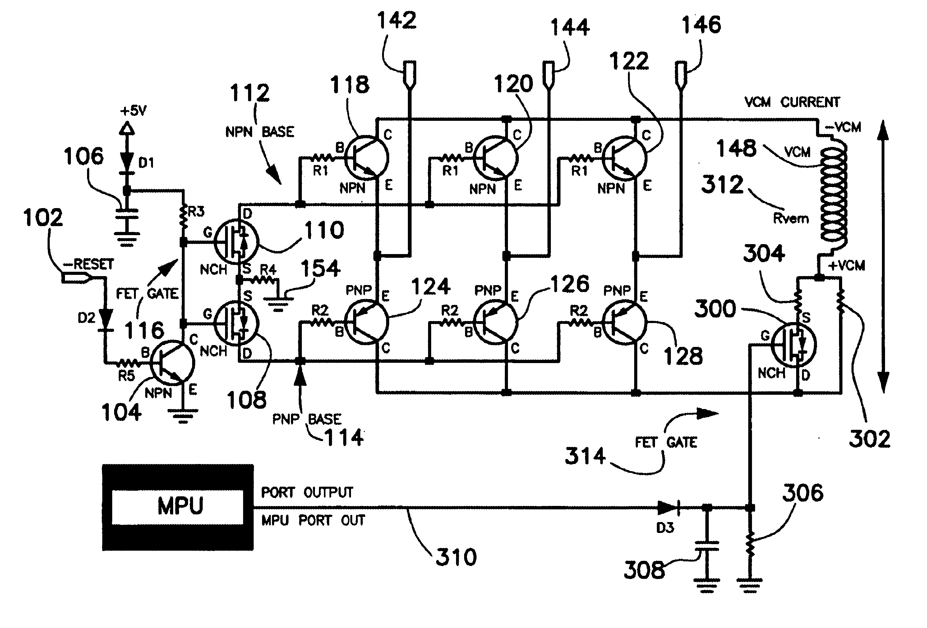
In one embodiment, the resistance of one part of the retract circuit is controlled to control the back-emf current flowing into a voice coil motor. A signal from the Main Processor Unit controls the increase or decrease in the resistance of the circuit.

Problems solved by technology

However, unlike AC power, battery power will get depleted as the notebook is being operated.
The trade-off for this lower power consumption is a decrease in RPM of the spindle motor which directly leads to a decreased performance in data access time.
FET rectifiers are active rectifiers, which have potentially the highest efficiency, but are significantly more complex.
Retract systems are designed to provide a specific current to the actuator; this current must be high enough to successfully park the actuator under all expected conditions (temperature, humidity, age, etc. and for the full range of manufacturing tolerances (torque constant of spindle and actuator, resistance of spindle and actuator, ramp friction, flex cable tension, etc. but no higher--too much retract current results in excessive shock to the fragile head-gimbal assemblies as they climb the L / UL ramp and the actuator impacts its crash stop.

Method used


Image

  • Actuator retract circuit for dual speed hard disk drive
  • Actuator retract circuit for dual speed hard disk drive
  • Actuator retract circuit for dual speed hard disk drive

Examples


Embodiment Construction

Although the invention is described as embodied in a hard disk drive with a spindle motor, the invention also applies to other motor systems and applications requiring dual / multiple speed controls such as CD-ROM drives, DVD drives, floppy disk drives, and even video camcorders for example. Accordingly, the following preferred embodiment of the invention is set forth without any loss of generality to, and without imposing limitations upon, the claimed invention.

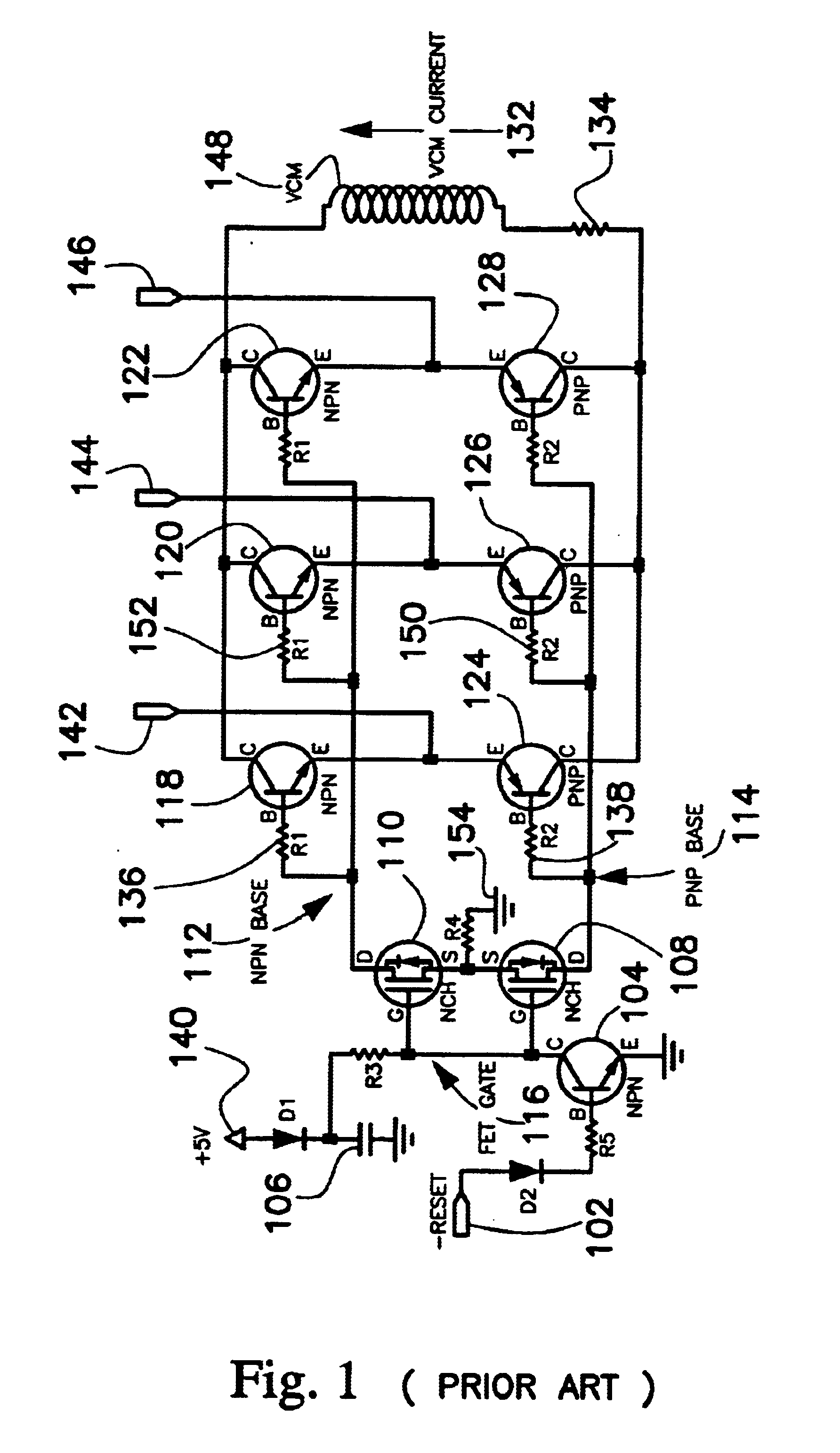
FIG. 1 shows a power-off retract system currently in use in single speed load / unload hard disk drives. This power-off retract system parks the actuator on the ramp in the case of an unexpected power off condition. The circuit uses a full-wave 3-phase rectifier with bipolar transistors to minimize voltage drop.

FIG. 15 is a table listing components used in a specific implementation of the conventional retract circuit illustrated in FIG. 1.

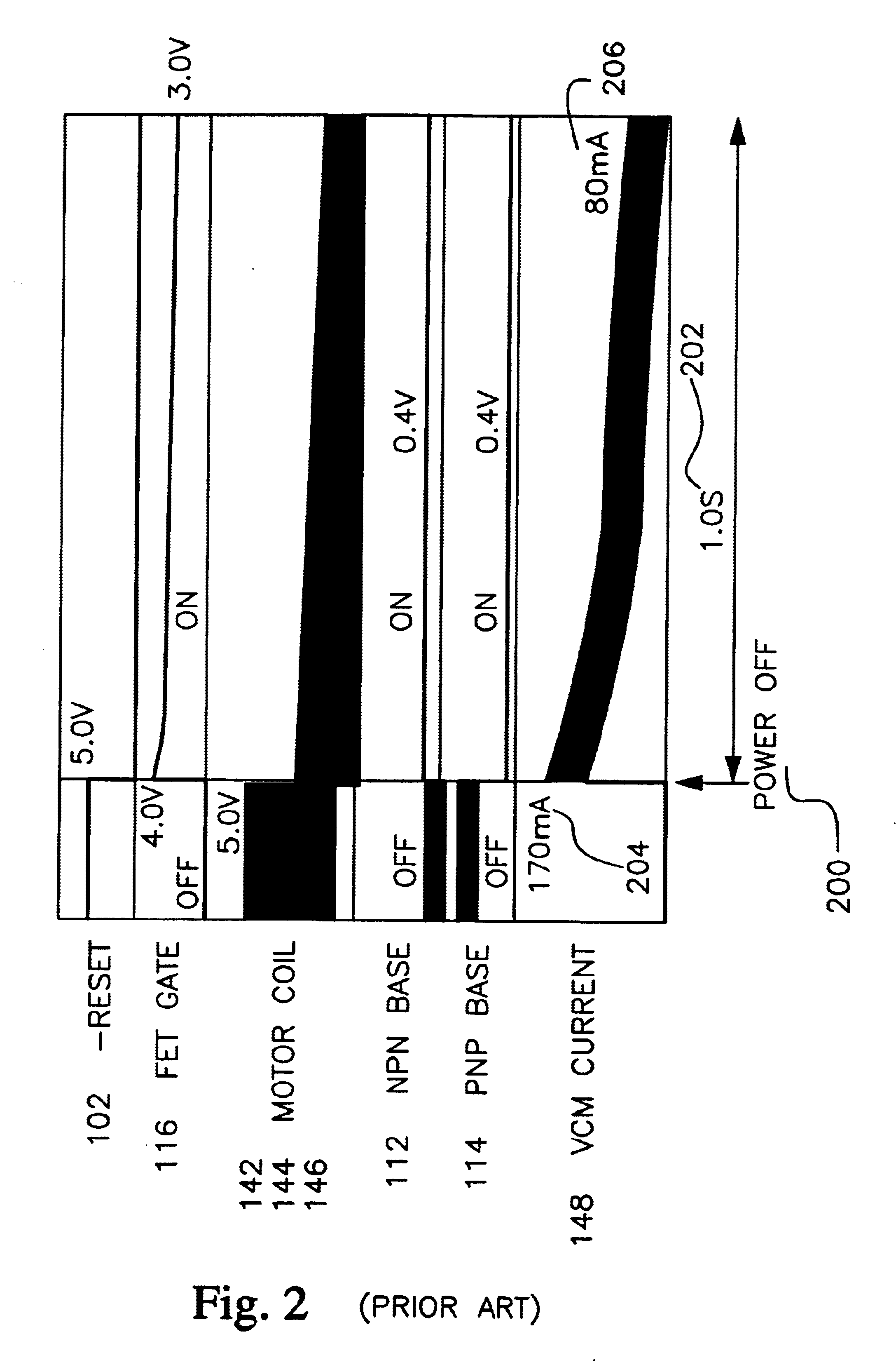
The states of the components in the circuit is summarized in the table below:

During normal ...


PUM

PropertyMeasurementUnit
voltageaaaaaaaaaa
currentaaaaaaaaaa
resistanceaaaaaaaaaa

Abstract

A dual speed hard drive system with an actuator retract system capable of retracting the actuator at approximately the same speed and power in both speed modes. In one embodiment, the control of resistance is used to control the amount of back-emf current supplied to the voice coil motor. In another embodiment, the circuit selectively restrict which spindle motor winding is allowed to supply back-emf current to the voice coil motor. In yet another embodiment, a voltage or a current regulator is used to control the current flowing into the voice coil motor. In all three embodiments, the amount of back-emf current supplied to the voice coil motor is proportional to the power and speed at which the actuator is being retracted.

Description

The present invention relates to the actuator retract systems in hard disk drives and more particularly to the actuator retract systems in hard disk drives with dual mode spindle motor control.DESCRIPTION OF THE RELATED ARTPortable computing devices, particularly notebook computers, are gaining popularity in recent years due to their compact size, weight, and mobility. Notebook computers can operate either from AC power or from battery power. However, unlike AC power, battery power will get depleted as the notebook is being operated. The hard disk drive (HDD) is one of the devices in a notebook that uses large amounts of power when in operation. Therefore, the spindle motors in hard disk drives are intentionally operated at low speeds, measured in revolutions per minute (RPM), to minimize power consumption during battery operation. The trade-off for this lower power consumption is a decrease in RPM of the spindle motor which directly leads to a decreased performance in data access t...

Claims


Application Information

Patent Timeline
Patent Type & Authority Patents(United States)
IPC IPC(8): G11B19/04G11B21/12G11B5/54
CPCG11B5/54G11B21/12G11B19/04
Inventor ALBRECHT, THOMAS ROBERTYAMAMOTO, SATOSHI
Owner HITACHI GLOBAL STORAGE TECH NETHERLANDS BV
Learn More