Master disc manufacturing apparatus

a manufacturing apparatus and master disc technology, applied in nanoinformatics, instruments, record information storage, etc., can solve the problems of limited recording resolution and inability to prepare high-precision master discs, and achieve high-density discs and high precision

Inactive Publication Date: 2003-11-18
PIONEER CORP
View PDF3 Cites 21 Cited by
  • Summary
  • Abstract
  • Description
  • Claims
  • Application Information

AI Technical Summary

Benefits of technology

The present invention has been made in view of the problems mentioned above, and the object of the present invention is to provide a high precision master manufacturing apparatus which is capable of manufacturing a high-density disc.

Problems solved by technology

Recording resolution, however, is limited by the spot diameter of a laser beam for recording in the manufacturing process of a master (i.e., a master disc or a stamper) of a recording medium using a conventional laser beam in a visible or ultraviolet wavelength range.
However, a practical master manufacturing apparatus capable of preparing high-precision masters has not appeared yet.

Method used


Image

  • Master disc manufacturing apparatus
  • Master disc manufacturing apparatus
  • Master disc manufacturing apparatus

Examples


first embodiment

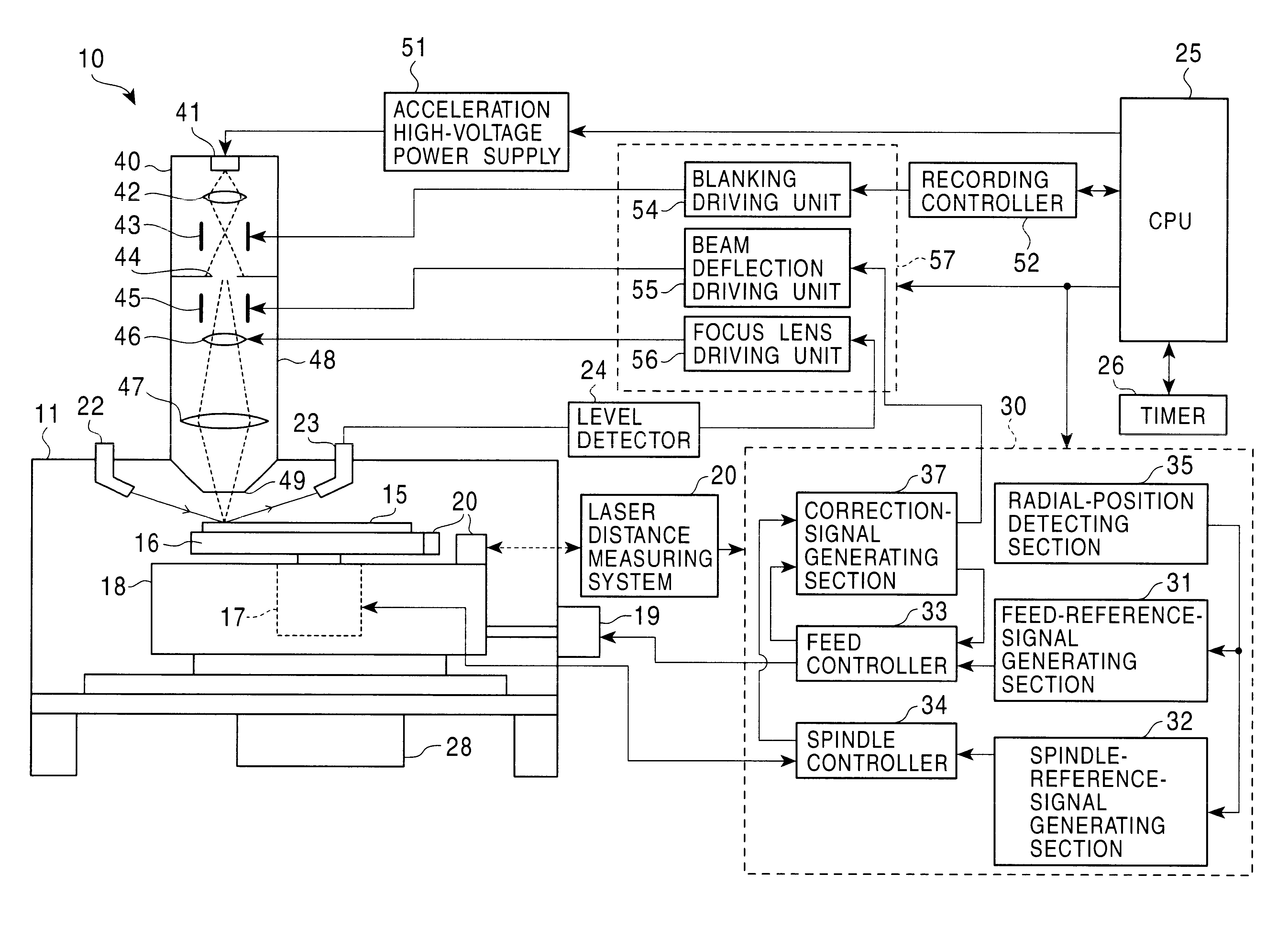
FIG. 1 is a block diagram illustrating one example of a master manufacturing apparatus according to the first embodiment of the present invention, which uses an electron beam. The outline of the manufacturing process of a master employing an electron beam exposure is described below.

The electron beam exposure is executed in a vacuum environment since the electron beam has such a characteristic as to be attenuated considerably in the atmospheric pressure. Therefore, an electron gun and driving units including a rotating unit and a moving unit for a substrate of the master are used in a vacuum environment. The manufacturing process will be described below for a master of an optical disc as an example.

For manufacturing a master of an optical disc, for example, a silicon (Si) plate is used as a substrate. The silicon substrate is coated with an electron beam resist on the principal or main surface. The substrate coated with the electron beam resist is rotated, and irradiated with an ele...

second embodiment

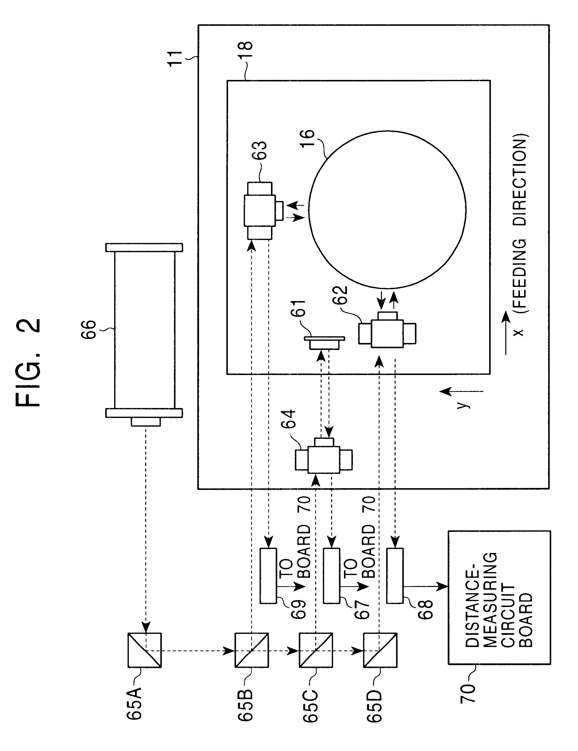
The following describes a second embodiment of the present invention. The configuration of the master manufacturing apparatus 10 is similar to that of the first embodiment.

FIG. 6 is a block diagram showing the configuration of the deflection-correction-signal generating section 37A. An encoder pulse signal ("n" pulses per rotation; e.g., 4096 pulses per rotation) indicating the rotational angle of the spindle motor 17, an encoder pulse reference signal (e.g., 1 pulse per rotation) indicating the rotational reference position and a clock signal (CK) from the laser distance measuring system 20 are supplied to the address data generating section 72. The address data generating section 72 counts encoder pulses based on the encoder pulse reference signal. For processing data every predetermined rotational angle, an address of, for example, 10 bits (=1024) according to the rotational angle is generated from the count value. The addresses are supplied to individual circuits in the deflecti...


PUM

PropertyMeasurementUnit
diameteraaaaaaaaaa
angleaaaaaaaaaa
distancesaaaaaaaaaa

Abstract

An apparatus of manufacturing a master by irradiating an electron beam on a substrate mounted on a turntable includes a rotation drive section for rotating the turntable; first and second correction-signal generating sections for respectively detecting first and second asynchronous components of rotational fluctuation of the turntable in a predetermined direction and in a direction perpendicular to the predetermined direction to generate first and second correction signals; and a deflection control section for controlling the electron beam deflection on the basis of the first and second correction signals.

Description

1. Field of the InventionThe present invention relates to a manufacturing apparatus of a master disc by irradiating an electron beam on a substrate.2. Description of the Related ArtA variety of large-capacity recording media are under development for recording image / audio data and digital data thereon. An optical disc such as a DVD (Digital Versatile Disc) is one example of the recording media. Research and development are now under progress for increasing the recording capacity to, for example, 30 GB (Giga-Bytes) for the optical disc having a diameter of 12 cm. Also, a hard disk platter for magnetic recording having large capacity is also under development.Recording resolution, however, is limited by the spot diameter of a laser beam for recording in the manufacturing process of a master (i.e., a master disc or a stamper) of a recording medium using a conventional laser beam in a visible or ultraviolet wavelength range. Investigations have been made for manufacturing the master (i....

Claims


Application Information

Patent Timeline
Patent Type & Authority Patents(United States)
IPC IPC(8): G11B7/26H01J37/304H01J37/30
CPCB82Y10/00B82Y40/00G11B7/26H01J37/304H01J37/3174G11B7/261H01J2237/3175H01J2237/3045
Inventor KAMIMURA, KENJIKURIYAMA, KAZUMIKUMASAKA, OSAMUKANEDA, HIROKISONE, MASAMIIWATA, TAKEHARUKOBAYASHI, MASAKI
Owner PIONEER CORP
Why Eureka
Try Eureka