Knit-in slide fastener

a technology of knitin and fasteners, which is applied in the direction of snap fasteners, flat warp knitting machines, knitting, etc., can solve the problems of inconvenience in appearance, poor appearance, and remarkable inconvenien

Inactive Publication Date: 2003-11-25
YKK CORP
View PDF10 Cites 10 Cited by
  • Summary
  • Abstract
  • Description
  • Claims
  • Application Information

AI Technical Summary

Benefits of technology

If heat treatment such as thermal setting is carried out after the fastener stringer is manufactured, likewise the knit-in slide fastener which the present invention aims at, hardness and tension of the yarn itself are heightened. Therefore, the yarns tend to be cut off easily due to interference with the aforementioned sewing needle. Particularly, if a small-diameter yarn which is very flexible is used, the yarn is more likely to be cut off.
The present invention has been achieved to solve the above described problems, and a concrete object of the invention is to provide a knit-in slide fastener in which when end portions of a fastener element row are mounted directly to clothes by sewing, any of the yarns that compose the fastener element mounting portion of the fastener tape is never cut off due to an interference with a sewing needle, so that the yarns of the fastener element mounting portion are prevented from being frayed, thereby ensuring an excellent durability.
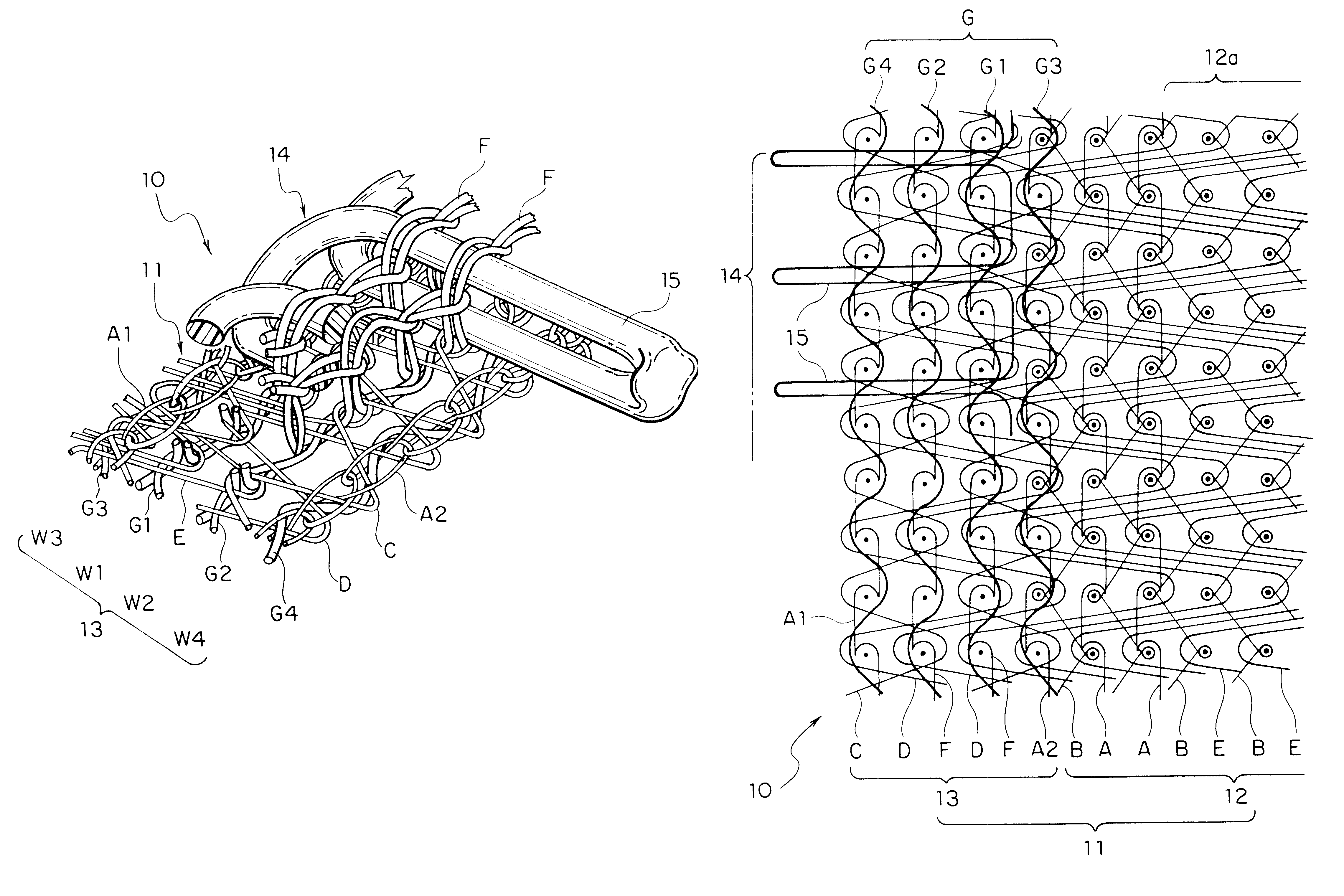
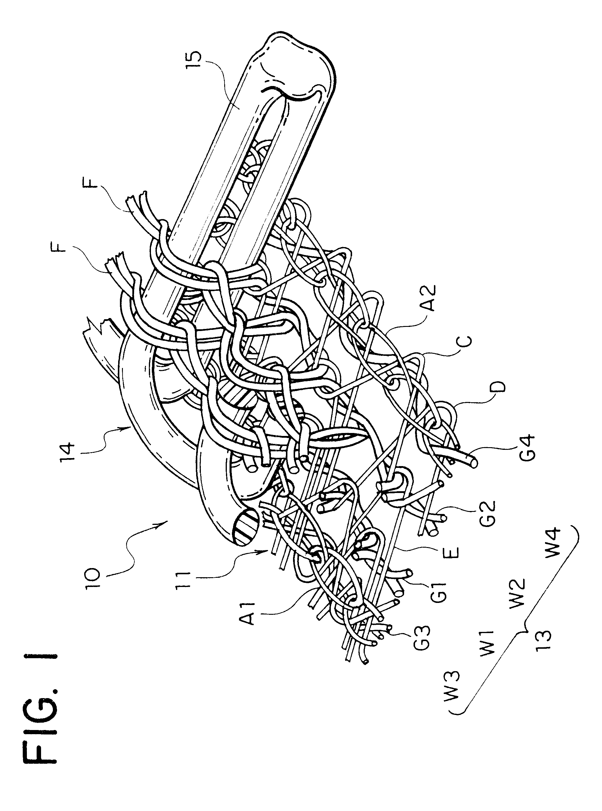
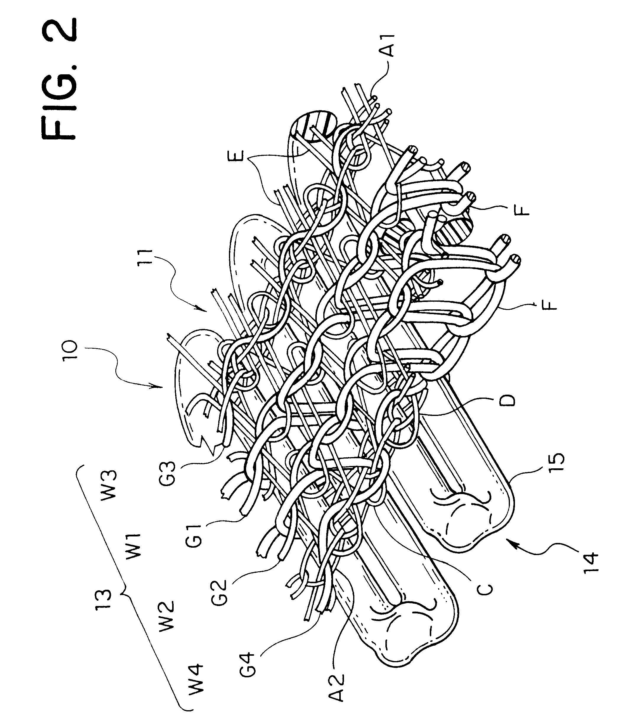
According to the present invention, the textured yarn having the above described structure as this fixing knitting yarn is used. Thus, when an end portion of the fastener element row of the fastener stringer with no end stop is attached to clothes by sewing, even if the sewing needle interferes with the strongly stretched fastener element fixing knitting yarn so that a tip of the sewing needle is pierced into that knitting yarn, a number of crimped fibers which compose each fixing knitting yarn are warped laterally and stretched only locally. As a result, the sewing needle can pass through between a number of the fibers, so that it never cuts off an entire part of the yarn. Further, even if the sewing needle is pierced into one of the composition fibers of the fixing knitting yarn and then cut off the fiber, no fraying occurs in the fibers because the cut off fiber is entangled with the other composition fibers in a complicated style at every predetermined interval.
Generally, in this kind of the slide fastener, as disclosed in Japanese Patent Application Laid-Open No. 11-187909, it is preferable to provide all the yarns which compose the fastener element mounting portion with the same dry heat shrinkage ratio because a strong tension is increased in the fixing knitting yarn coupled with the foundation structure, which strides over the upper leg portion of the fastener element, by heat treatment after having been knitted. On the other hand, in order to secure a dimensional stability of the fastener stringer and a predetermined mounting strength of the fastener element, it is preferable to set the dry heat shrinkage of all the composition yarns in the fastener element mounting portion to be higher than the dry heat shrinkage ratio of the composition yarns in the fastener tape main portion of the fastener tape.
The reason is that the strength of each fiber is lower and likely to be cut off because the aforementioned fixing knitting yarn is a bundle of a number of fine fibers so that no unreasonable tension force is to be given. Further, the fixing knitting yarn having such a low shrinkage ratio can secure a total strength required for the fixing knitting yarn because the strength can be increased when each composition fiber is stretched.
Further, a dimensional stability of the fastener stringer and a fixing strength necessary for the fastener element row can be obtained by setting the dry heat shrinkage ratio of the composition yarns other than the fixing knitting yarn in the fastener element mounting portion to be high and by setting the dry heat shrinkage ratio of the fastener tape main portion of the fastener tape to be substantially as low as the fixing knitting yarn.

Problems solved by technology

Because each of these upper and lower stoppers is usually composed of small pieces made of metallic material or synthetic resin material, their mounting portions of the stoppers are protruded outward when such a slide fastener is sewed to trousers or a skirt, so that its appearance is not good.
Particularly, in the case of an upper stopper, which is mounted in a separate manner to the right and left, it is difficult to fit the slider to the same upper stopper, so that a fastener portion between the slider and the upper stopper is separated during use, thereby causing an inconvenience in appearance.
However, if the slide fastener is attached with stoppers as mentioned above, the inconvenience becomes remarkable.
Therefore, the yarns tend to be cut off easily due to interference with the aforementioned sewing needle.

Method used


Image

  • Knit-in slide fastener
  • Knit-in slide fastener
  • Knit-in slide fastener

Examples


Embodiment Construction

Hereinafter, an embodiment of the present invention will be described in detail with reference to examples shown in the accompanying drawings.

In the meantime, FIG. 1 shows that the respective knitting yarns are loosened around the fastener element mounting portion while the fastener tape main portion is omitted for facilitating understanding of the drawing. However, it shall be understood that the knitting pattern and the entangling portions of each knitting yarn are tightened firmly in its actual state. Although the same figure shows diversified sizes of the knitting yarns, this only aims to facilitate understanding. Actually, the size of each knitting yarn may be selected arbitrarily considering the function of the knit-in slide fastener and the formation of the knitting pattern.

Further, the present invention should not be restricted to the knitting structure illustrated in the embodiment. For example, the present invention can be applied to not only the case where various kinds o...


PUM


Abstract

There is provided a knit-in slide fastener in which a continuous fastener element row is knitted simultaneously with the knitting of a warp knitted fastener tape at a fastener element mounting portion on a longitudinal side edge portion of the fastener tape. Since a yarn composed of ordinary long fibers, or a textured yarn is employed as a fixing knitting yarn for the fastener element mounting portion, even if a sewing needle is pierced into the textured yarn, the fixing knitting yarn is never cut off because the sewing needle passes through a number of fibers which compose the textured yarn. Further, even when part of the fibers are cut off, no fraying occurs in the yarns, so that the fastener element row at the cut off portions does not separate from the fastener tape.

Description

BACKGROUND OF INVENTIONThe present invention relates to a knit-in slide fastener in which a fastener tape thereof is composed of a warp knitting structure and a continuous fastener element row formed of thermoplastic-synthetic-resin-made monofilament is fixed along a fastener element mounting portion on a longitudinal side edge of the fastener tape simultaneously with knitting of the fastener tape. More particularly, it relates to a knit-in slide fastener which makes it possible to stabilize pitches between the fastener elements by forming a knitting structure of the fastener element mounting portion to be dense and to prevent any cutoff of composition yarns in the fastener element mounting portion due to a sewing needle when end portions of the fastener element rows are fixed.For example, Japanese Patent Application Laid-Open No.8-314 has disclosed a knit-in slide fastener in which a continuous fastener element row is knitted in and fixed in the fastener element mounting portion fo...

Claims


Application Information

Patent Timeline
Patent Type & Authority Patents(United States)
IPC IPC(8): A44B19/34A44B19/24A44B19/56D04B21/20
CPCA44B19/343D04B21/16D10B2501/0631Y10T24/252Y10T24/2523Y10T24/2527Y10T24/2529D10B2401/04A44B19/56
Inventor MATSUDA, YOSHIO
Owner YKK CORP
Why Eureka
Try Eureka