Burner assembly

a burner and assembly technology, applied in the field of burner assembly, can solve the problems of increasing the cost of manufacture, increasing the labor required to operate the burner, and increasing the likelihood of repair, so as to reduce the amount of co emissions in the combustion space, improve the combustion intensity, and reduce the amount of combustion space required

Inactive Publication Date: 2003-11-25
ASTEC
View PDF22 Cites 37 Cited by
  • Summary
  • Abstract
  • Description
  • Claims
  • Application Information

AI Technical Summary

Benefits of technology

Accordingly, it is an advantage of the invention claimed herein to provide an apparatus for producing a stable flame configuration that has a short flame length and a narrow flame diameter. It is also an advantage of the invention to provide an apparatus for producing a flame configuration that is adapted for use on a wide variety of different-sized combustion chambers having different-sized combustion spaces. It is another advantage of the invention to provide an apparatus that more rapidly, completely, and evenly mixes fuel and air, thereby improving combustion intensity, reducing the combustion space required in the asphalt drum, and reducing CO emissions in the combustion space. It is still another advantage of the invention to provide an apparatus that reduces the temperature of the dryer drum breech plate. It is yet another advantage of a preferred embodiment of the invention to provide an apparatus that achieves reduced NOx emissions. It is a further advantage of the invention to provide an apparatus that eliminates the need for adjustable spin vanes in order to achieve a desired flame configuration. It is a still further advantage of the invention to provide an apparatus that is less complicated and expensive to manufacture, operate and maintain than conventional burner assemblies.

Problems solved by technology

However, conventional burner assemblies suffer from several disadvantages.
For example, conventional burner assemblies are incapable of producing a flame configuration satisfactory for asphalt production in a variety of different-sized combustion chambers.
Adjustable spin vanes, however, increase the cost of manufacture, the likelihood of repair, and the amount of labor required to operate the burner.
These burner assemblies, however, do not utilize the castellated elements to maximum advantage.

Method used


Image

  • Burner assembly
  • Burner assembly
  • Burner assembly

Examples


Embodiment Construction

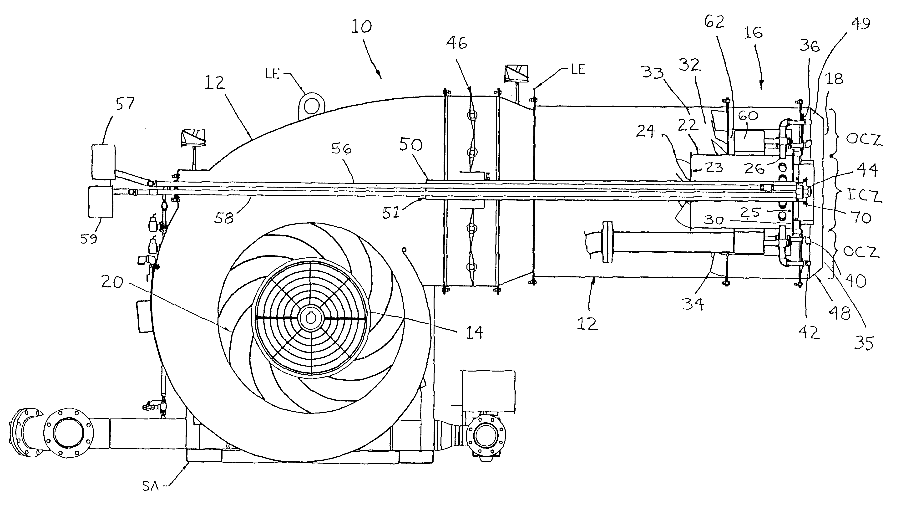
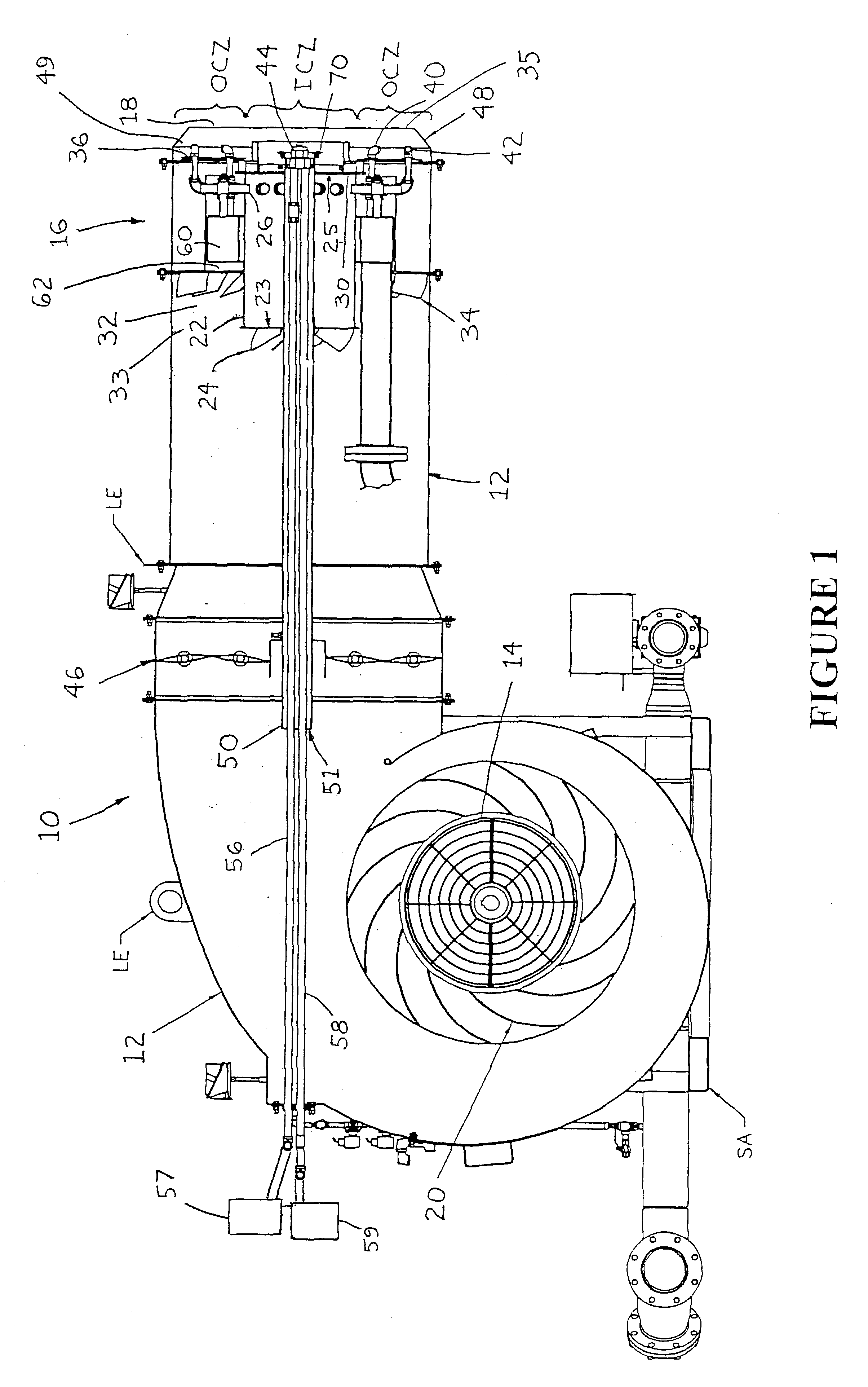
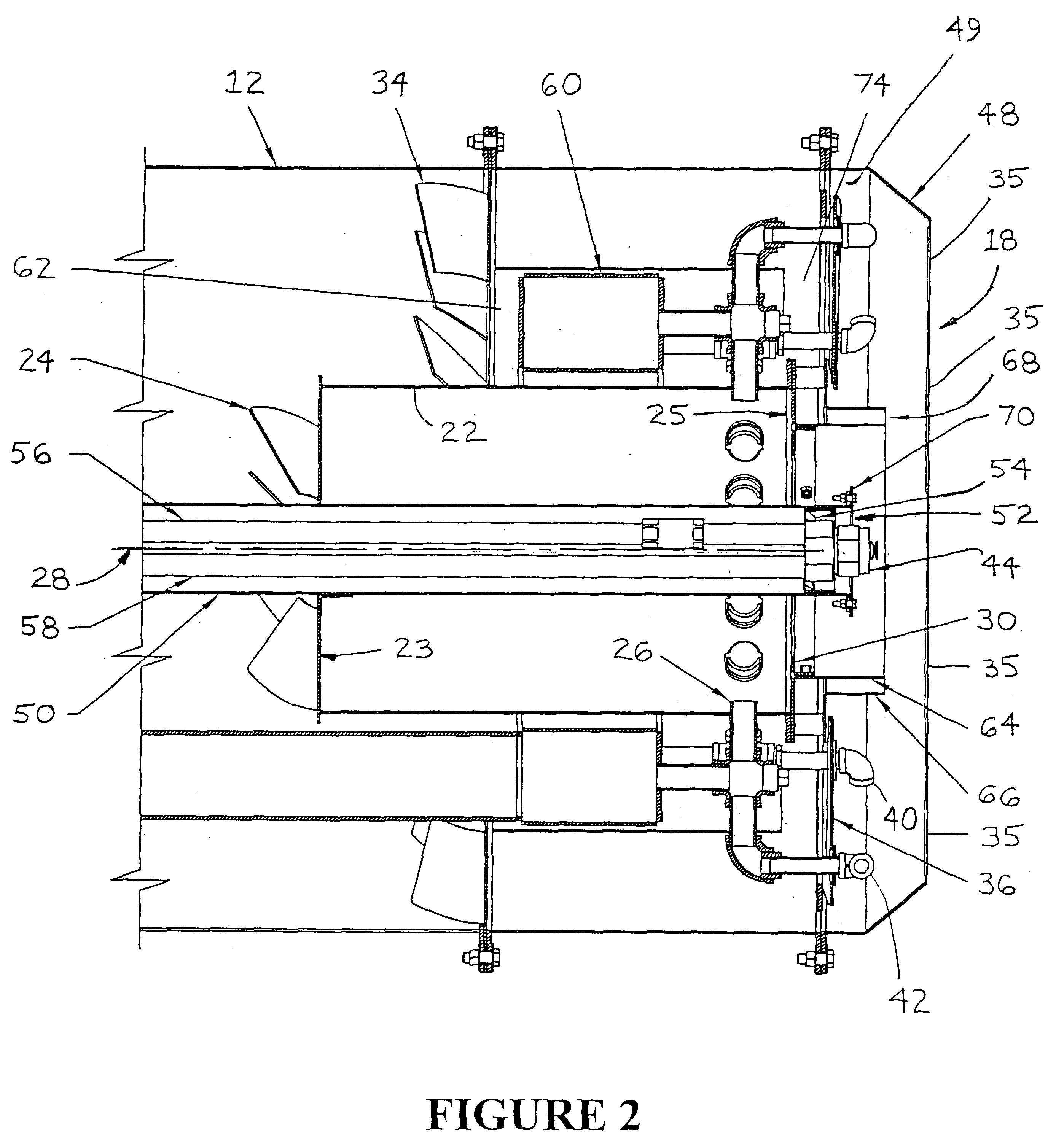
Referring now to the drawings, the apparatus of the invention claimed herein is illustrated by FIGS. 1 through 11. FIG. 1 illustrates a preferred embodiment of the burner assembly in accordance with the present invention. The burner assembly is designated generally by reference numeral 10. Burner assembly 10 is built on skid assembly SA having lifting eyes LE that allow the assembly to be handled with a fork truck or hoist. The preferred burner assembly is adapted to selectively fire on a gaseous fuel such as natural gas or a liquid fuel such as fuel oil, or both.

As shown in FIG. 1, burner assembly 10 comprises housing 12 having air inlet 14 and burner end 16 downstream from the air inlet. Housing 12 generally contains the working components of the burner assembly and provides an outer shell within which combustion air may be pressurized, conveyed from the air inlet to the burner end, and mixed with fuel to produce a flame at the burner end of the housing. Air inlet 14 is adapted to...


PUM


Abstract

A burner assembly including a housing having an air inlet and a burner end. An impeller that is mounted in the housing is in communication with the air inlet and adapted to direct air toward the burner end of the housing. The burner assembly also includes an inner air tube that is mounted in the burner end of the housing so as to define an inner combustion zone and an outer combustion zone. The assembly further includes a plurality of radiation plates that are mounted in the burner end of the housing adjacent to the outer combustion zone, an inner air spin vane that is mounted on the inner air tube so as to direct some of the air from the impeller into the inner combustion zone, an inner gas injection nozzle mounted on the inner air tube so as to direct gaseous fuel into the inner combustion zone, an outer air spin vane that is mounted in the burner end of the housing so as to direct some of the air from the impeller into the outer combustion zone, and a plurality of outer gas injection nozzles that are mounted in the burner end of the housing so as to direct gaseous fuel into the outer combustion zone. A first castellated ring is mounted around the periphery of the inner air tube, and a second castellated ring is mounted around the periphery of the burner end of the housing.

Description

This invention relates generally to an improved burner assembly, and more particularly, to an improved fuel burner assembly for heating and drying aggregate materials used in connection with the production of hot mix asphalt.BACKGROUND AND DESCRIPTION OF THE PRIOR ARTIt is known to use a fuel burner assembly to heat and dry aggregate materials used in connection with the production of hot mix asphalt. See, e.g., U.S. Pat. Nos. 5,700,143; 5,511,970; 4,559,009; and 4,298,337. However, conventional burner assemblies suffer from several disadvantages. For example, conventional burner assemblies are incapable of producing a flame configuration satisfactory for asphalt production in a variety of different-sized combustion chambers. As a result, burner assemblies typically include adjustable spin vanes to accommodate different-sized combustion chambers. For example, U.S. Pat. No. 6,488,496 of Feese et al. describes a compact combination burner with an adjustable spin rack. Adjustable spin ...

Claims


Application Information

Patent Timeline
Patent Type & Authority Patents(United States)
IPC IPC(8): F23D14/24F23D14/00F23D14/36
CPCF23D14/36F23D14/24
Inventor IRWIN, BRUCE C.FOUNTAIN, RUSSELLSWANSON, MALCOLMUNJAKOTI, JOSEPHSWANSON, MICHAEL
Owner ASTEC
Why Eureka
Try Eureka