Variable gain low-noise amplifier for a wireless terminal

a low-noise amplifier and wireless terminal technology, applied in the circuit field, can solve the problems of imposing unwanted spurious signals on foreign terminals, reducing the bias current accompanied by linear degradation, and waste of transmitter's battery

Inactive Publication Date: 2003-12-02
GCT SEMICONDUCTOR INC
View PDF6 Cites 55 Cited by
  • Summary
  • Abstract
  • Description
  • Claims
  • Application Information

AI Technical Summary

Benefits of technology

Another object of the invention is to provide a low-noise amplifier and method of operating same that reduces or avoids clipping its output signal when receiving a large input signal.
Another object of the invention is to provide a method and apparatus capable of controlling the gain of a transmitter's preamplifier so as not to waste the battery and not to overdrive the next stage (the power amplifier).

Problems solved by technology

Such a strong signal may impose unwanted spurious signals on foreign terminals near the transmitter, and waste the transmitter's battery.
Additionally, the circuit for amplification in a receiving terminal may clip and distort its output signal for a large magnitude input.
Unfortunately, the reduction of the bias current is accompanied by degradation of linearity caused by an unwanted cutoff of the driving transistor.
An abrupt change of LNA's gain inherent in the bypass operation makes it hard to simultaneously achieve good linearity and the desired noise performance.

Method used


Image

  • Variable gain low-noise amplifier for a wireless terminal
  • Variable gain low-noise amplifier for a wireless terminal
  • Variable gain low-noise amplifier for a wireless terminal

Examples


Embodiment Construction

A gain-control method and apparatus for a low-noise amplifier (e.g., tuned) and a preamplifier used in wireless communication systems will be described according to preferred embodiments of the present invention. For example, one preferred embodiment of the gain control method and apparatus can be adopted for the circuitry in a wireless terminal and implemented in an LNA or a preamplifier. However, the present invention is not interpreted to be so limited. Further, the invention is applicable to any type of device technologies, such as the bipolar-junction transistor (BJT) or junction field-effect transistor (JFET). For purposes of illustration, preferred embodiments according to the invention will be described below using metal-oxide-semiconductor field-effect transistor (MOSFET) technology.

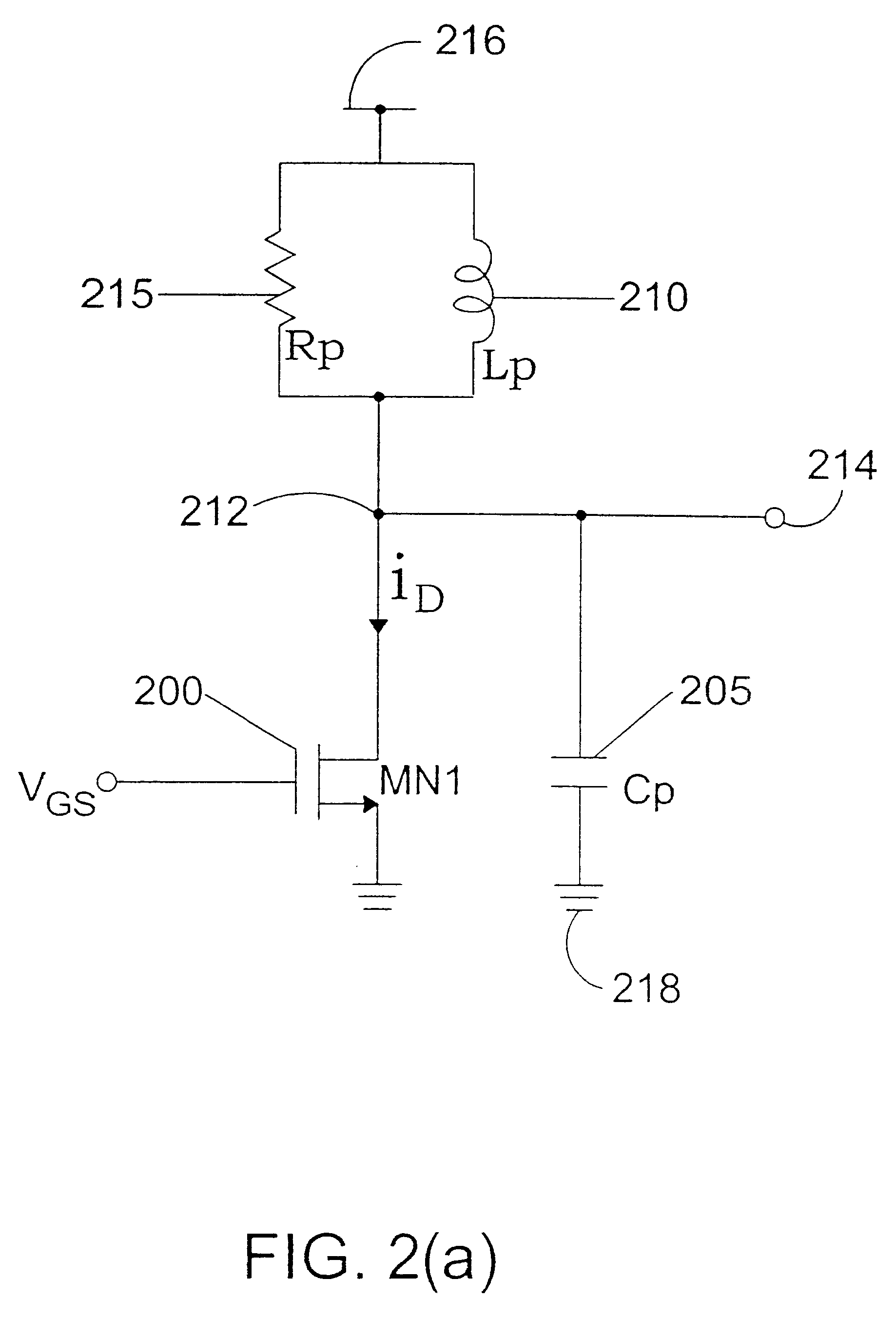
FIG. 2(a) is a diagram that shows a preferred embodiment of an amplifier according to the present invention. FIG. 2(a) shows a tuned LNA which has a desired gain in a narrow band of frequencies....


PUM


Abstract

A variable gain, low noise amplifier is described, which is suitable as the input amplifier for a wireless terminal, or as the pre-amplifier stage of a wireless terminal transmitter. The amplifier may achieve variable gain by deploying a network of transistors in a parallel array, each independently selectable by a PMOS switch, and providing the variable resistance for the resonant circuit. Power dissipation can also be mitigated by using a network of driving transistors, each independently selectable by a PMOS switch. The resonant frequency of the amplifier may be made tunable by providing a selection of optional pull-up capacitors.

Description

BACKGROUND OF THE INVENTION1. Field of the InventionThis invention relates generally to a circuit for controlling gain in low noise amplifiers (LNA's) or in preamplifiers, and more specifically to gain control circuitry for use in LNAs or preamplifiers used in wireless communication systems.2. Background of the Related ArtIn wireless communication, the incident signal at a terminal unit (e.g. an handset) has various magnitudes, depending on the environment of the radio-wave propagation (including the distance between the terminal and the base station). A strongly radiated signal from a transmitting terminal is helpful to a remote station, but is of less use if the station is nearby. Such a strong signal may impose unwanted spurious signals on foreign terminals near the transmitter, and waste the transmitter's battery. Additionally, the circuit for amplification in a receiving terminal may clip and distort its output signal for a large magnitude input.In general, the inward and the o...

Claims


Application Information

Patent Timeline
Patent Type & Authority Patents(United States)
IPC IPC(8): H03G1/00H03F3/16H03G3/10H03G3/18
CPCH03F1/223H03F3/195H03F3/72H03G1/0088H03F2200/294H03F2200/391H03F2200/451H03F2203/7236H03F2200/378H03G3/10
Inventor PARK, JOONBAEJEONG, HOE-SAMLEE, SEUNG-WOOKLEE, WON-SEOKLEE, KYEONGHO
Owner GCT SEMICONDUCTOR INC
Why Eureka
Try Eureka