Optical amplification repeater and optical amplification repeating and transmitting system

a technology of optical amplification and transmitting system, applied in the field of optical amplification repeater and optical amplification repeating and transmitting system, can solve the problems of affecting the quality of communication, requiring troublesome procedures, and coping with the increase or decrease of wavelengths

Inactive Publication Date: 2003-12-02
MITSUBISHI ELECTRIC CORP
View PDF30 Cites 26 Cited by
  • Summary
  • Abstract
  • Description
  • Claims
  • Application Information

AI Technical Summary

Problems solved by technology

As a result of this, very troublesome procedure is required for coping with increase or decrease of the number of wavelengths.
Consequently, in the case where one of the wavelength-multiplexed light signals of wavelengths .lambda.1 to .lambda.n is not transmitted due to some failure in sender equipment, by way of example, the messaging procedure such as mentioned above will not be in time for coping with the change of the number of wavelengths, thus bringing about corresponding changes in the powers of the other wavelengths, which of course will exert adverse influence to the quality of communication.

Method used


Image

  • Optical amplification repeater and optical amplification repeating and transmitting system
  • Optical amplification repeater and optical amplification repeating and transmitting system
  • Optical amplification repeater and optical amplification repeating and transmitting system

Examples


embodiment 1

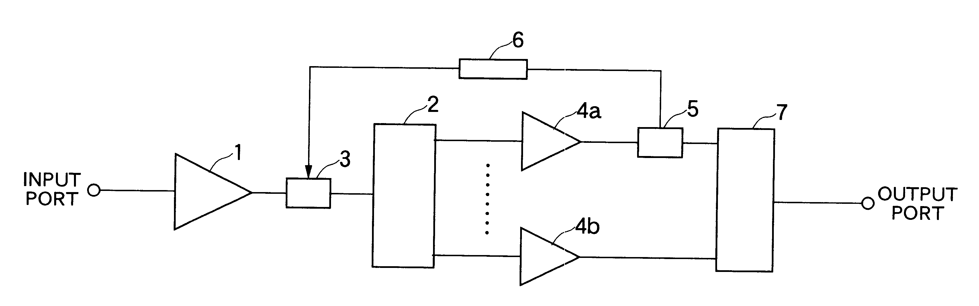
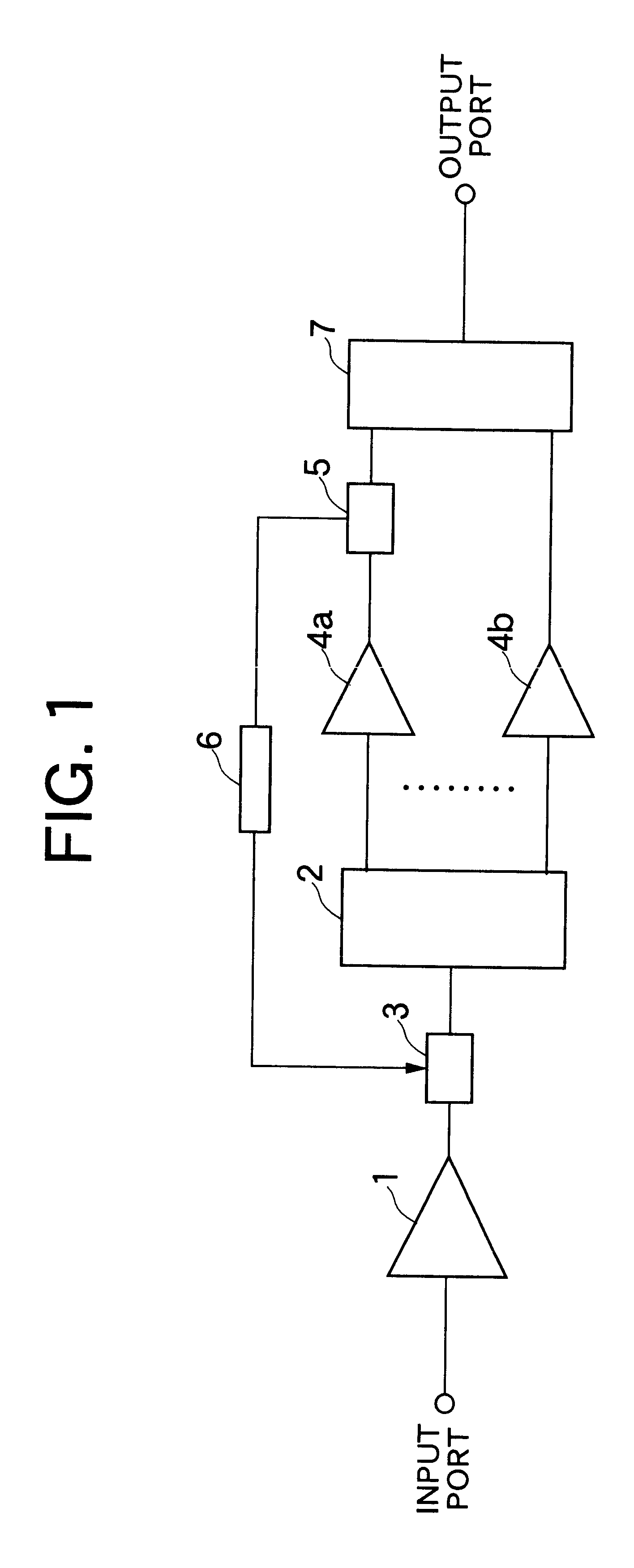
FIG. 1 is a block diagram showing a configuration or structure of an optical amplifying repeater apparatus according to a first embodiment of the present invention. In FIG. 1, reference numeral 1 denotes a first fixed-gain optical amplifier, numeral 2 denotes an optical demultiplexer, numeral 3 denotes an adjustable optical attenuator, numerals 4a; 4b denote fixed-gain optical amplifiers #1-#n, numeral 5 denotes a monitoring light branching device, numeral 6 denotes an adjustable attenuator control circuit, and reference numeral 7 denotes an optical multiplexer.

Next, operation of the optical amplifying repeater apparatus will be described. Referring to FIG. 1, the first fixed-gain optical amplifier 1 is designed to amplify wavelength-multiplexed light signals of n bands, i.e., wavelengths .lambda.11 to .lambda.1n (first band), .lambda.21 to .lambda.2n (secondband), . . . , .lambda.n1 to .lambda.nn (n-th band) with a predetermined gain.

In the present state of the art, such a system h...

embodiment 2

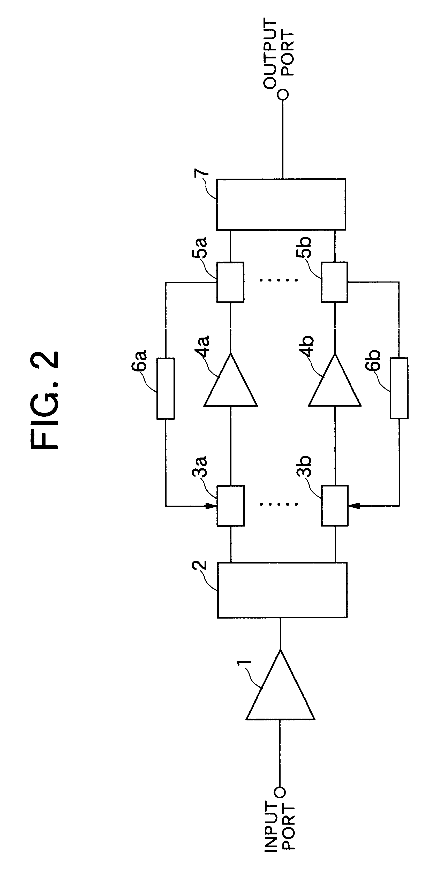
FIG. 2 is a block diagram showing a configuration of the optical amplifying repeater apparatus according to a second embodiment of the invention. In FIG. 2, reference numeral 1 denotes a first fixed-gain optical amplifier, numeral 2 denotes an optical demultiplexer, numerals 3a; 3b denote adjustable optical attenuators #1-#n, respectively, numerals 4a; 4b denote fixed-gain optical amplifiers #1-#n, respectively, numerals 5a; 5b denote monitoring light branching devices #1-#n, respectively, numerals 6a; 6b denote adjustable attenuator control circuits #1-#n, respectively, and reference numeral 7 denotes an optical multiplexer.

Next, operation of the optical amplifying repeater apparatus according to the instant embodiment will be described. Referring to FIG. 2, the first fixed-gain optical amplifier 1 is designed to amplify wavelength-multiplexed light signals of n bands, i.e., wavelengths 11 to .lambda.1n (first band), .lambda.21 to .lambda.2n (second band), . . . , .lambda.n1 to .la...

embodiment 3

FIG. 3 is a block diagram showing a configuration or structure of an optical amplifying repeater apparatus according to a third embodiment of the invention. In FIG. 3, reference numeral 8 denotes an optical fiber, numeral 9 denotes an optical coupling device and reference numeral 10 denotes a pumping light source. In the figure, components same as or equivalent to those of the optical amplifying repeater apparatus described previous by reference to FIG. 2 are denoted by like reference symbols, and description thereof is omitted.

Operation of the optical amplifying repeater apparatus according to the instant embodiment will be described. In the optical amplifying repeater apparatus now under consideration, the pumping light source 10 sends out pumping light injected to the optical fiber 8 by way of the optical coupling device 9 for effectuating the stimulated Raman amplification. Since the stimulated Raman amplifier is difficult to be subjected to gain saturation when compared with th...


PUM


Abstract

Light signals of first to n-th bands amplified en bloc undergo proper attenuation through an adjustable optical attenuator in conformance with attenuation in an optical fiber connected to input of an optical amplifying repeater apparatus, whereon the light signals are demultiplexed or separated into individual bands and amplified by first to n-th fixed-gain optical amplifiers (#1, . . . , #n) each having a high fixed gain in the respective bands to be subsequently multiplexed by an optical multiplexer and then sent out onto a transmission line. A monitoring light branching device extracts a part of light power of a specific monitoring wavelength, which is then fed to an adjustable attenuator control circuit which controls the attenuation factor of the adjustable optical attenuator so that the light power of the specific wavelength remains constant. The gain of the optical amplifying repeater apparatus at the specific wavelength can thus be determined. By employing as the optical amplifying medium a substantially homogeneous medium, the gain for the other wavelengths can be fixed. The optical amplifying repeater apparatus whose gain is essentially independent of the change in the number of the wavelengths can thus be realized.

Description

The present invention relates to an optical amplifying repeater apparatus implemented by using as a repeater an optical amplifier which is constituted by employing an optical fiber doped with laser activating substance(s) such as rare-earth element(s), transition metal(s) or the like and also relates to an optical amplifying / repeating transmission system in which the optical amplifying repeater apparatuses are made use of.BACKGROUND TECHNIQUESWhen compared with the conventional optical repeater having 3R (Reshaping, Retiming, Regenerating) functions known heretofore, the optical fiber amplifier has desirable features such as independency on the transmission rate, susceptibility to simplified implementation of the repeater, possibility of implementation with large capacity owing to the wavelength multiplexing capability and others. Thus, the optical fiber amplif ier is expected to promise a key component which is capable of enhancing flexibility of the optical communication system. I...

Claims


Application Information

Patent Timeline
Patent Type & Authority Patents(United States)
IPC IPC(8): H04B10/17H04J14/02H04B10/294H04B10/296
CPCH04B10/2941H04J14/0221H04B10/296H04B2210/258
Inventor MOTOSHIMA, KUNIAKISHIMIZU, KATSUHIRONAKAGAWA, JUNICHISUZUKI, NAOKI
Owner MITSUBISHI ELECTRIC CORP
Why Eureka
Try Eureka