Liquid spray device and cutting method

Inactive Publication Date: 2003-12-09
FUJI BC ENG
View PDF55 Cites 69 Cited by
  • Summary
  • Abstract
  • Description
  • Claims
  • Application Information

AI Technical Summary

Benefits of technology

It is an object of the present invention to provide a liquid spray device capable of reliably producing a fine spray

Problems solved by technology

In a method of directly spraying liquid oil to the target object, the amount to be sprayed becomes too large, so that it takes a long time to remove excess oil, thus reducing the productivity.
Furthermore, since the excess oil scatters around the device, it has been necessary to prevent the working environment from being contaminated.
Furthermore, a pump and an oil vessel are formed separately from the main body, thus making the structur

Method used


Image

  • Liquid spray device and cutting method
  • Liquid spray device and cutting method
  • Liquid spray device and cutting method

Examples


embodiment 1

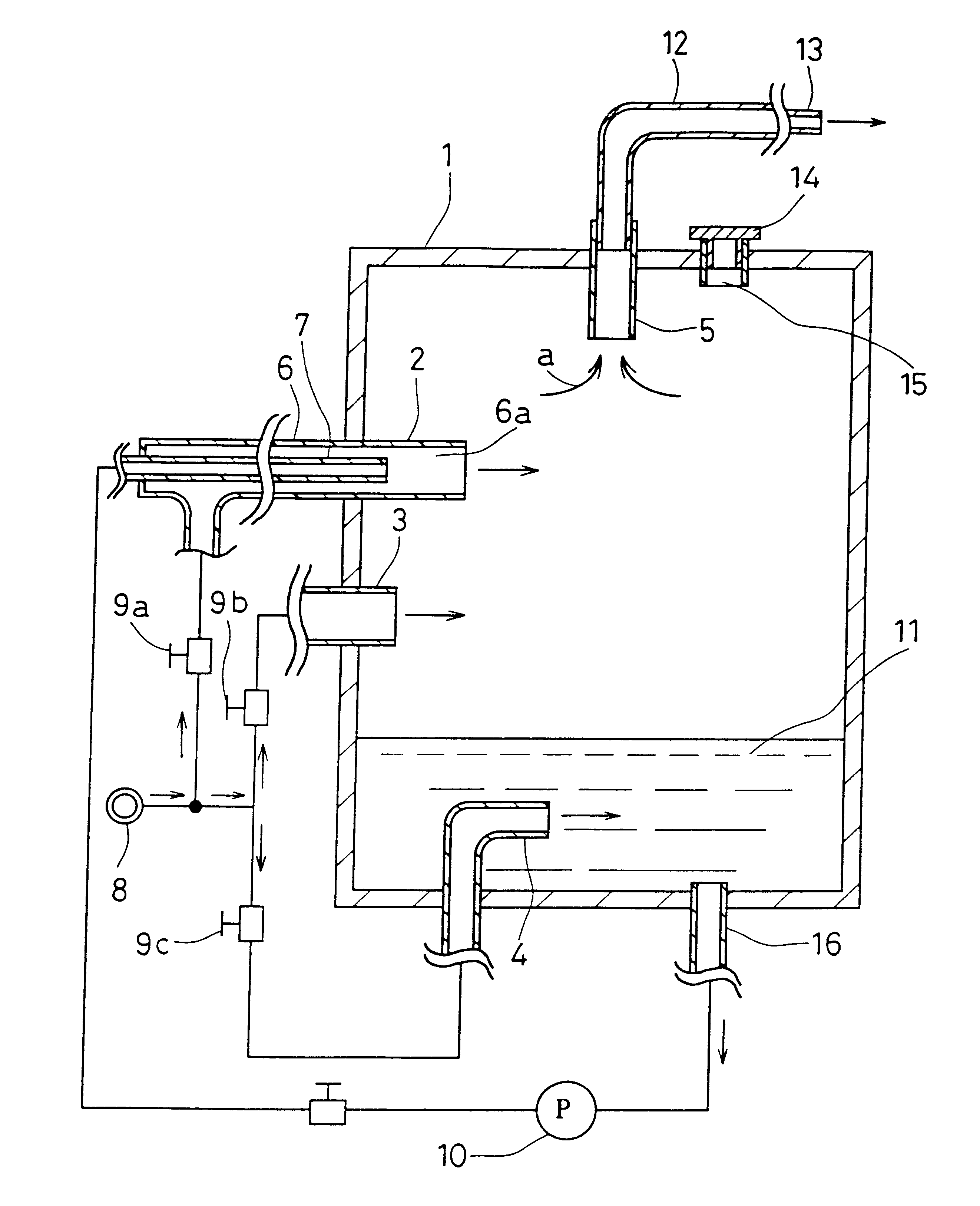
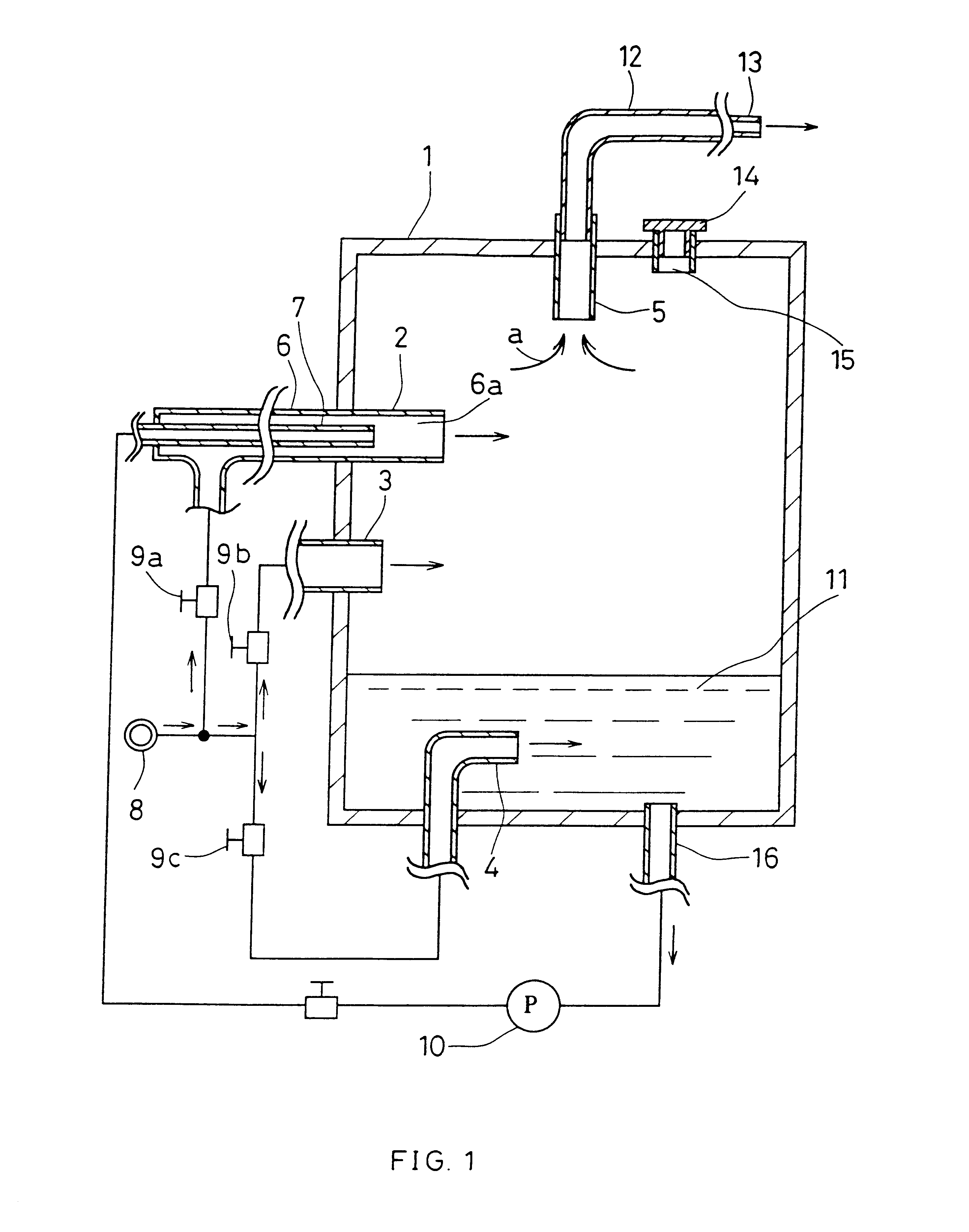
FIG. 1 is a vertical cross sectional view showing a liquid spray device according to Embodiment 1. Reference numeral 1 denotes a container. The container 1 is provided with a spray injection nozzle 2, a gas injection nozzle 3, an under-liquid nozzle 4 and a spray feeding pipe 5.

The spray injection nozzle 2 has a dual structure formed of a gas tube 6 and an oil tube 7. The oil tube 7 passes through the gas tube 6. The gas tube 6 is connected to a gas source 8 and the flow rate of injecting gas can be regulated by a gas flow rate regulating valve 9a. The oil tube 7 is connected to the oil pump 10. For the gas discharged from the gas source 8, for example, air is used.

Furthermore, at the tip of the spray injection nozzle 2 inside the container 1, the tip of the oil tube 7 enters the inside of the gas tube 6. At the nozzle tip 6a, oil supplied from the oil pump 10 and gas supplied from the gas source 8 are mixed with each other, and thus oil spray is produced and injected into the conta...

second embodiment 2

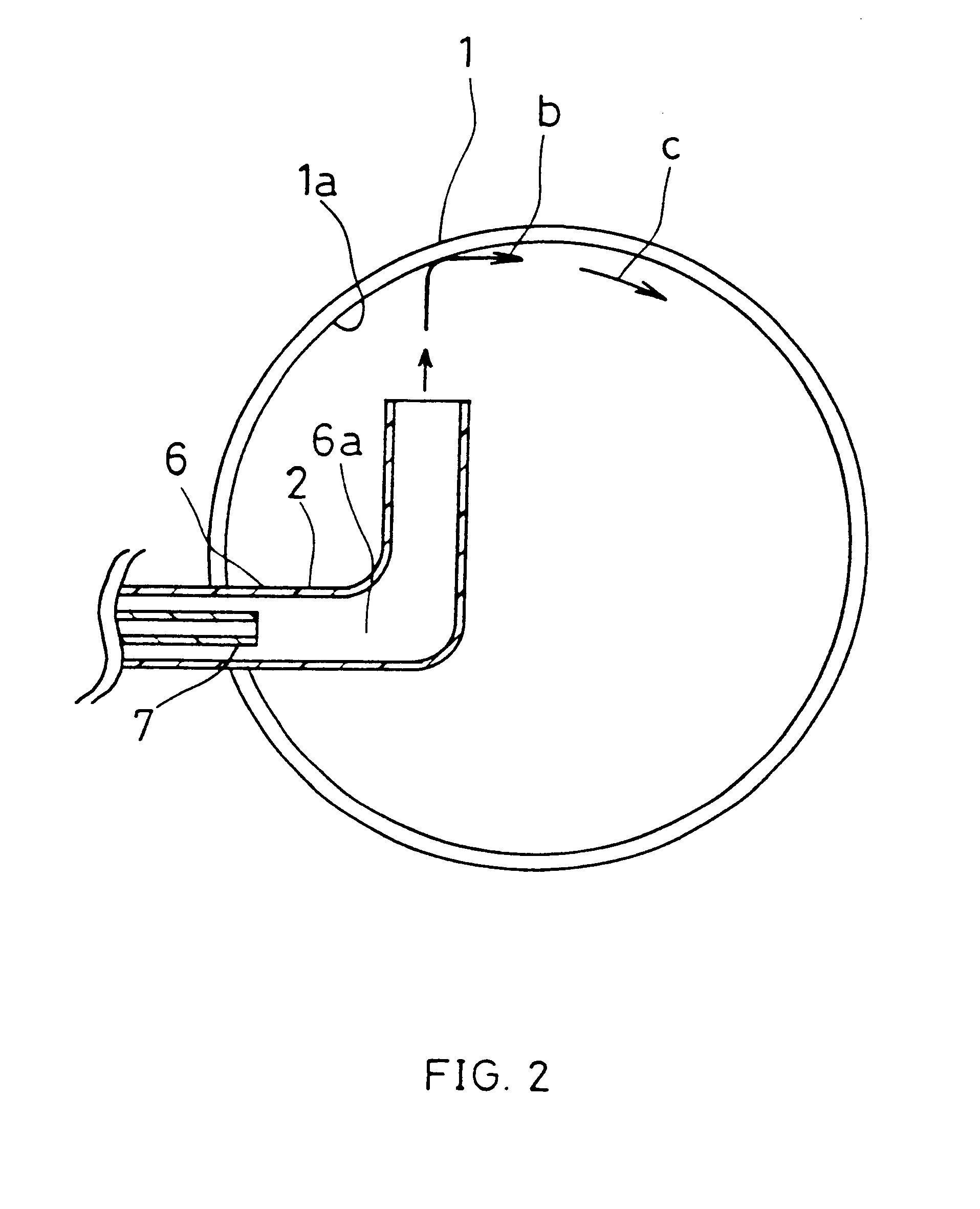
The device of Embodiment 2 is the same as that of Embodiment 1. The device of Embodiment 2 is characterized by the relationship between the tip portion of the spray injection nozzle 2 and the internal wall face of the container 1. With such a device of Embodiment 1, the length between the tip portion of the spray injection nozzle 2 and the tip portion of the spray feeding pipe 5 is set to be sufficiently long so that, it is securely possible to drop the oil spray having a large particle size or oil droplets onto the liquid surface.

The device of Embodiment 2 is effective in a case where the container is relatively small and the sufficient length between the tip portion of the spray injection nozzle 2 and the tip portion of the spray feeding pipe 5 cannot be obtained.

FIG. 2 is a horizontal cross sectional view showing a liquid spray device according to Embodiment 2. The tip portion of the spray injection nozzle 2 is located so that most of injected flow amount strikes the face of the ...

embodiment 3

The device according to Embodiment 3 is the same as that of the Embodiment 1 except for the location relationship between the tip portion of the spray injection nozzle and the liquid surface of oil.

FIG. 3 is a vertical cross sectional view showing a liquid spray device according to Embodiment 3. The device of FIG. 3 is the same as that of FIG. 1 except for the locations of the spray injection nozzle 2 and the gas injection nozzle 3. Therefore, the part such as a gas circuit etc., is not shown herein. The tip portion of the spray injection nozzle 2 is directed to the liquid surface side of the oil 11. The length between the tip and the liquid surface is made to be close so that the spouting of the oil 11 from the liquid surface can be prevented. Therefore, most of the injected spray flow from the spray injection nozzle strikes the liquid surface directly before being fed to the spray feeding pipe 5.

Fine oil spray is hardly absorbed into the liquid surface even if it strikes the liqui...


PUM


Abstract

A liquid spray device, comprising a container (1), a spray injection nozzle (2) for injecting oil spray into the container (1), a spray feeding path (5) for feeding oil spray in the container (1) to the outside of the container (1), oil (11) stored in the container (1), a gas exhaust port provided in the oil (11) by discharging gas into the oil (11), whereby the flow velocity of the oil spray in the spray feeding path can be increased and the amount of oil spray can be increased because an internal pressure of the container can be increased and an oil spray different from the oil spray from the spray injection nozzle can be produced.

Description

The present invention relates to a liquid spray device for feeding spray (liquid particulates) in a container to spray liquid to a target object and a cutting method using the same. More particularly, the present invention relates to a liquid spray device for supplying a cutting member of a machine tool, for example, a machining center, a grinding machine, a turning machine, or the like, with a cutting oil and to a cutting method using the same.Hitherto, during machining, oil is sprayed to a target object, for example, a work piece or a tool, etc., in order to enhance the machining accuracy or to extend the life of tools. In a method of directly spraying liquid oil to the target object, the amount to be sprayed becomes too large, so that it takes a long time to remove excess oil, thus reducing the productivity. Furthermore, since the excess oil scatters around the device, it has been necessary to prevent the working environment from being contaminated.When oil is sprayed in the form...

Claims


Application Information

Patent Timeline
IPC IPC(8): B05B7/00B05B7/04B05B7/24B05B7/26B23Q11/10F16N7/34
CPCB05B7/0012B05B7/0441B05B7/24
Inventor INOUE, TSUTOMU
Owner FUJI BC ENG
Why Eureka
Try Eureka