Sub-rigid fast-form barrier system

a fast-form barrier and rigid technology, applied in the field of rigid fast-form barrier systems, can solve the problems of affecting the variable cost of labor of every nail, screw, nut&bolt, compound wedge,

Inactive Publication Date: 2003-12-16
NELSON THOMAS PAGE
View PDF11 Cites 49 Cited by
  • Summary
  • Abstract
  • Description
  • Claims
  • Application Information

AI Technical Summary

Benefits of technology

advance methods of building concrete formwork,
co-ordinate methods of building concrete formwork with house framing members whereby this invention may be employed using the permanent housing materials for the purpose of building concrete foundation walls prior to recycling said materials as house framing and sheathing,
advance methods of re-moveably installing concrete formwork, in order that areas confined within the enclosure that formwork provides for concrete, may be easily accessed by a man and easily reformed, for removal of debris, prior to concrete placement,
advance methods of re-moveably installing concrete formwork, in order that areas confined within the enclosure that formwork provides for concrete, may be easily accessed by a man and easily reformed, for installation of a through-wall block-outs or sleeves, prior to concrete placement,
advance methods of re-moveably installing concrete formwork, in order that areas confined within the enclosure that formwork provides for concrete, may be easily accessed by a man and easily reformed, for installation or repairs to reinforcing steel, prior to concrete placement,
improve methods of re-moveably installing concrete formwork, in order that areas confined within the enclosure that formwork provides for concrete, may be easily accessed by a man and easily reformed, for installation of embedded structural plates, prior to concrete placement,

Problems solved by technology

None of the prior art searched by the inventor, reviewed, or found on the market displays a method similar to the Ratiocinative Interlocking Fast-Form Barrier System.
None of the prior art inventions singly or in combination meet all of the objectives established by this versatile interlocking barrier system.
Today every nail, screw, nut&bolt, and compound wedge impact the variable cost of labor.
These supernumeraries expose Bowden's method as labor intensive for today's market.
The main load-gathering beam of Bowden's invention is designed to be produced from sheet metal only, thereby limiting strength and integrity.
While Bowden teaches a method of extending transverse sub-members in repetition with the ability to overlap and stabilize a plurality of collateral vertical wales, he does not teach a method of ease and efficiency for extending his materials collaterally in a vertical direction.
Bowdens system is restricted to formwork applications and does not display the cubic content desired for permanent barriers.
Bowdens system does not complete formwork application and removal with the ease, versatility, and competence of the system claimed herein.
However the advancement ends there and the functionality while superior to Bowden's, suffers from all the same deficiencies stated above in relation to Bowden's.
Bowden and Chapman both lack the ability to remove plywood modules, or to remove subordinate beams with ease.
Talandis's method lacks versatility.
The Talandis method is not very practical for formwork or any other application when given the modular materials of our time.
Furthermore the Talandis system is restricted to formwork applications and does not display the cubic content desired for diversified barriers.
The Talandis system does not complete formwork application and removal with the ease and competence of the advanced system claimed herein.
However, this is the only practical application where the innovations may be applied.
Butt's and Hall's system suffers from a stockpile of many parts and pieces, and while bar joists offer strength and lightness, they suffer from lack of compact efficiency and extended stability.
While this system is designed to support concrete, it is not feasible for use as a rigid or sub-rigid wall as it displays no method of sheathing or retaining the plywood surface without the inclusion of screws, nails, bolts or the like.
Prior art does not display these advantages.
While we have experienced many advances in the development of our natural resources we have not seen many broad-based advances in their application.
With the world population increasing rapidly, sheltering humanity is a problem around the globe.

Method used


Image

  • Sub-rigid fast-form barrier system
  • Sub-rigid fast-form barrier system
  • Sub-rigid fast-form barrier system

Examples


Embodiment Construction

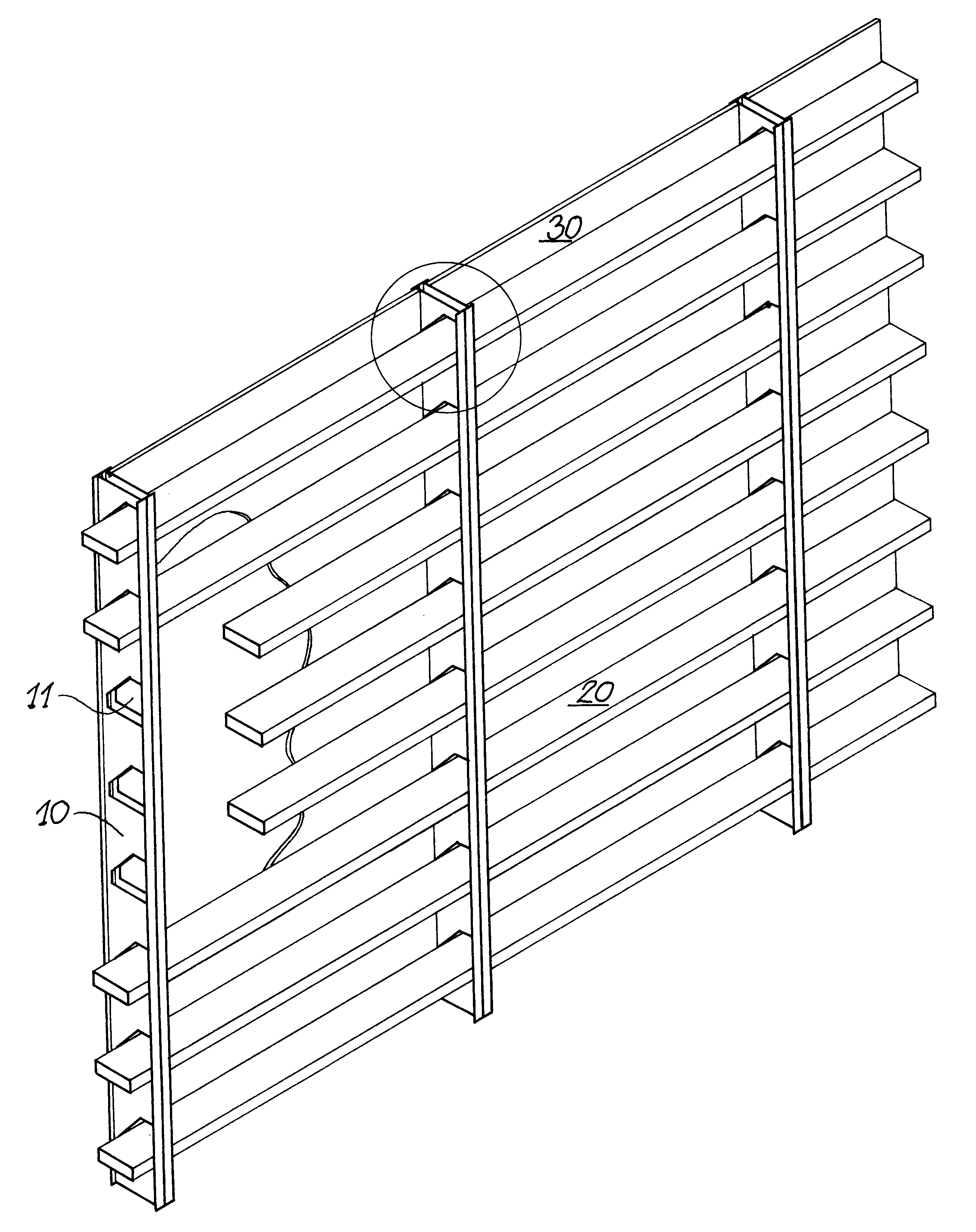
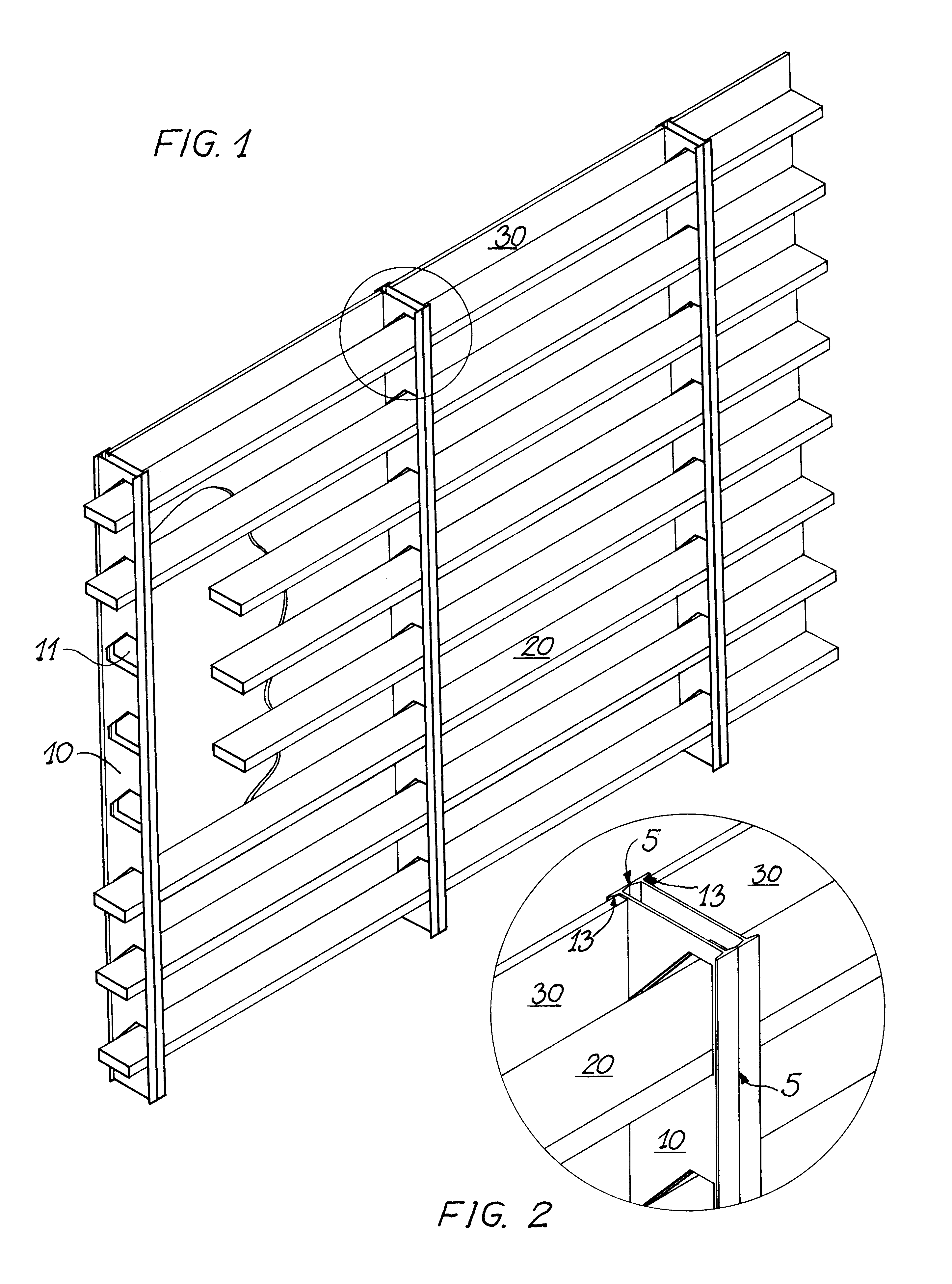
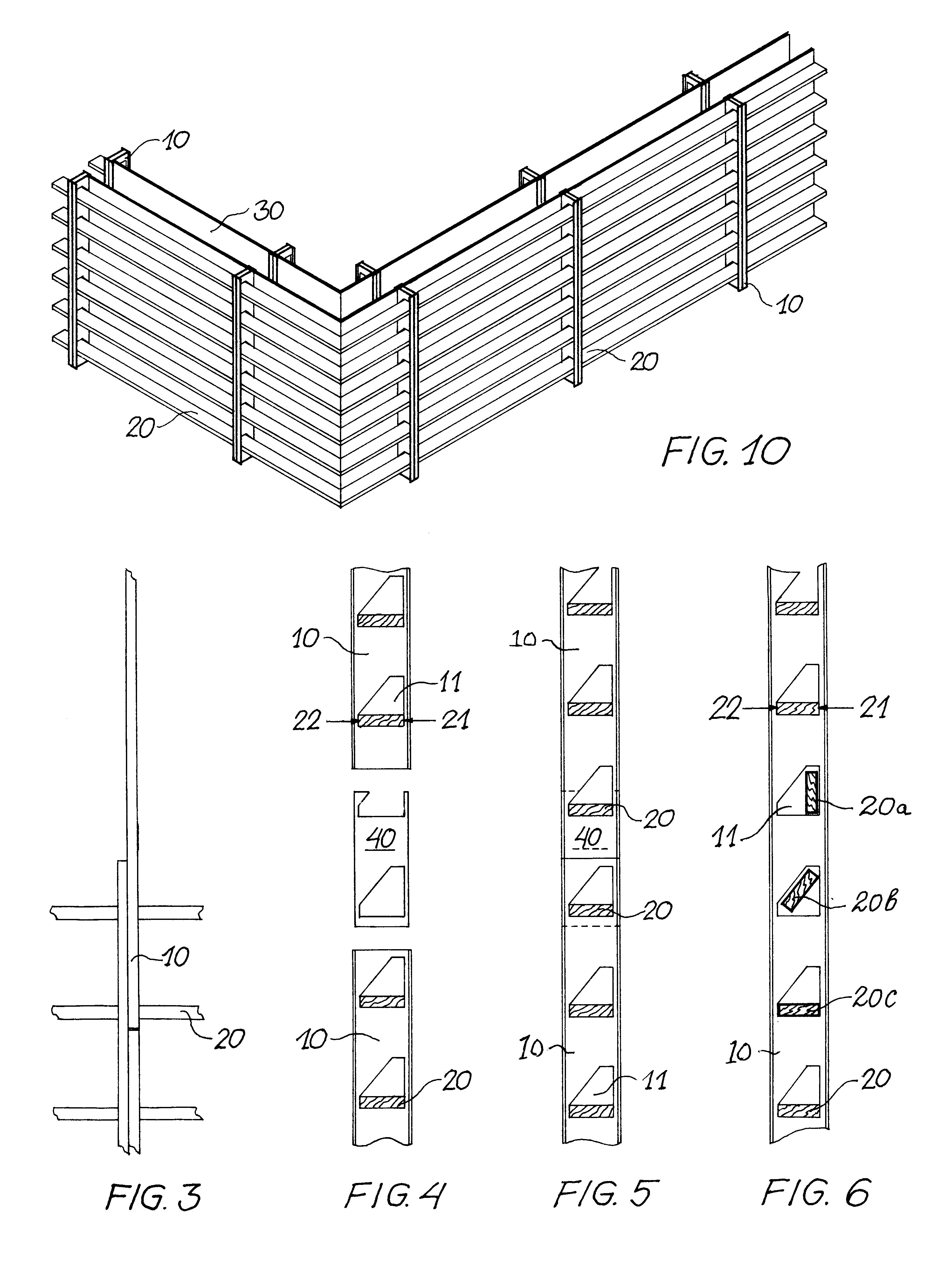
The Sub-Rigid Fast-Form Barrier System, disclosed herein, is remarkable in its simplicity and promises wide commercial application as the labor costs for construction become increasingly prohibitive.

In the world today time is money and the erection speed this system offers may well revolutionize conventional "post and beam" framing while transforming platform framing to a fast-form barrier system.

The invention is specifically aimed at calculated beam loading where barriers may be economically fabricated to withstand hurricane force winds. While the tie down system for housing walls and roofs is nothing novel, the tie-downs in concert with this fast-form system offers an economical composition that can easily increase or decrease the size of tys to meet estimated standard or eccentric loading. The fast-form system will offer insurance companies an insurable building procedure for any and all applications. When the barriers disclosed herein are utilized as concrete formwork, contracto...


PUM


Abstract

The invention disclosed herein is remarkable in its simplicity and promises wide commercial application as the labor costs for construction become increasingly prohibitive. The extraordinary absence of nails, screws, bolts, welds or any other fastening device allows these barriers to compete with many conventional barrier systems, such as those employed for fencing, vehicular trailer beds, removable stages, and scale models or toys of all fabrications mentioned plus many more. In this age time is money and the erection speed this barrier system offers may well revolutionize conventional "post and beam" framing. The invention is specifically aimed at eccentric beam loading where barriers must be economically fabricated to withstand hurricane force winds, earthquake reactions, or liquid concrete pressure in a sub-rigid manner. The Fast-Form System will offer insurers building products that will protect their interests for any and all applications. When the barriers disclosed herein are utilized for concrete formwork, contractors will have a new option that embraces standard building products, with barrier fabrication accomplished in half the time of the systems that precede it.

Description

"Joining" is the art form that this invention advances; with the joining of standard building materials, for manufacturing mass produced, efficient, commercial barriers, as the main objective.Relative to the application described herein, the inventor has a diversified background and experience in the industrial art of joining building materials.The ratiocinative combinatory logic is rooted in the inventor's knowledge and thirty years of experience in working with concrete form design and application. Formwork must be assembled quickly in a rigid or sub-rigid composition, maintained in a pre-engineered and static fabrication during concrete placement and subsequently dismantled and stockpiled for future multiple uses.While developing the ratiocinative interlocking barrier as a new concrete forming system, it became apparent that the post and beam type framing of this invention would offer an improved method for framing and sheathing houses or the like.While modeling the fast-form bar...

Claims


Application Information

Patent Timeline
Patent Type & Authority Patents(United States)
IPC IPC(8): E04G17/04E04G11/12E04B1/16E04G11/00E04B2/76E04G9/02E04B2/86E04B2/74
CPCE04B1/161E04B2/763E04G17/04E04G9/02E04G11/12E04B2/8635E04B2002/7466E04B2/8652
Inventor NELSON, THOMAS PAGE
Owner NELSON THOMAS PAGE
Why Eureka
Try Eureka