Sintered sprocket

a sprocket and sprocket technology, applied in the direction of solid-state diffusion coating, casting apparatus, natural mineral layered products, etc., can solve the problems of low precision of tooth surfaces, relatively high production costs, and low production costs, and achieve the effect of maximally increasing the density of the surfa

Inactive Publication Date: 2003-12-30
HONDA MOTOR CO LTD
View PDF2 Cites 6 Cited by
  • Summary
  • Abstract
  • Description
  • Claims
  • Application Information

AI Technical Summary

Benefits of technology

It is an object of the present invention to provide a sintered sprocket which can improve the surface pressure resistance without an expensive forging processing, and to provide a production method therefor.
In the sintered sprocket as constructed above, since the ferrite adjoins the voids, the ferrite is plastically deformed and the voids which are located inside the tooth surface are collapsed by carrying out a deformation processing, such as a rolling, on the tooth surface. As a result, volumes of the voids are reduced, and the density in the vicinity of the tooth surface is increased. The surface pressure resistance can be thereby improved while maintaining a high-precision tooth surface and the production costs are lower by using powder metallurgy techniques. In addition, since the internal base layer contains bainite, the strength and the hardness of the matrix is increased.
Ni and Mo contribute to generation of bainite by strengthening the matrix in the base layer and by improving the hardening property. In the case in which the Ni content and the Mo content are below 0.2%, respectively, the above effects are insufficient. In contrast, in the case in which the Ni content and the Mo content exceed 1.0%, martensite is easily deposited and the strength is lowered. The present invention may include the case in which the martensite coexists with the bainite.
It is desirable that the ferrite in the base layer be 40% or more by area, the density after rolling is thereby further increased, and the surface pressure resistance can be improved. In addition, it is desirable that a carbide layer be provided at the frontmost location which is outside of the base layer, and the surface pressure resistance can be thereby improved. The carbide layer can be formed by a carburizing processing.
In the production method for the sintered sprocket as described above, the ferrite plastically deforms by the rolling, the voids are thereby collapsed, and the density of the sprocket is increased. Diffusion of iron atoms occurs by carburizing and hardening, and the voids are further reduced. Therefore, the density of the surface of the sintered sprocket is increased, and the surface pressure resistance can be further improved. As a carburizing and hardening, high concentration carburizing carried out in a CO concentration of 0.1% or more by weight is preferable, and the surface pressure resistance can be thereby further improved.
In the production method for the sintered sprocket of the present invention, it is desirable that the ferrite on the base layer be 40% or more by area. In addition, it is desirable that the rolling width be 0.09 to 0.15 mm, and the density of the surface can thereby be maximally increased.

Problems solved by technology

In such a sprocket, although the precision of tooth surfaces and the surface pressure resistance are superior, there is a problem in that production costs are relatively high due to the forging processing which is carried out.
In such a sprocket, although the surface pressure resistance is sufficient, there are problems in that the production costs are hardly decreased since a machining processing is needed for press fractures, and in addition, in that the precision of the tooth surfaces is lower due to warping caused by the press processing.
In such a sprocket, although the precision of the tooth surfaces and the production costs are advantageous, there is a problem in that the surface pressure resistance is inferior.
In the case in which a sprocket is produced from a sintered material, although there is a problem in the surface pressure resistance as described above, the surface resistance is reduced by voids which inevitably exist inside the material.
However, the increase of the density is limited even in such a production method having many processes, and the surface pressure resistance of the tooth surface was insufficient.
In addition, although the density is increased by carrying out forging on a sintered material and the surface pressure resistance is thereby improved, there is the same problem as in the above in that the production costs are relatively high.

Method used


Image

  • Sintered sprocket
  • Sintered sprocket
  • Sintered sprocket

Examples


Embodiment Construction

In the following, the present invention will be explained in detail by referring to examples according to the present invention.

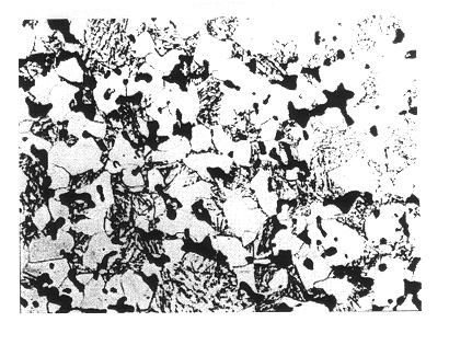
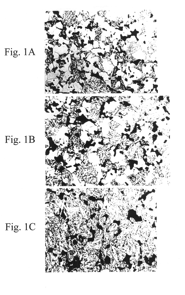
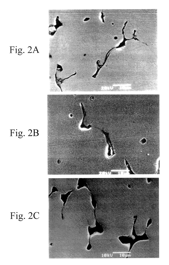
Powder consisting of Ni powder at 0.5% by volume, Mo powder at 0.5% by volume, graphite powder at 0.3 to 0.6% by volume, and iron powder as the balance, was compacted in a sprocket shape and was then sintered in air at 1150.+-.20.degree. C. for 60 minutes. Next, the sprocket was rolled to a rolling width of 0.09 mm, using a rolling apparatus shown in FIG. 3. In the figures, reference numeral 1 indicates a sprocket, and reference numerals 2 indicate dies. Gear teeth to be equal to those of the sprocket 1 were formed at a periphery of the die 2A. Tooth surfaces of the sprocket were pressed by sandwiching the sprocket 1 between two dies 2 and rotating the dies 2, and the gear teeth were thereby compacted in a specific tooth shape. The term "rolling width" refers to a pressing amount in a perpendicular direction to the tooth surface of the sprocket. With respec...


PUM

PropertyMeasurementUnit
widthaaaaaaaaaa
widthaaaaaaaaaa
densityaaaaaaaaaa

Abstract

A sintered sprocket is provided in which surface pressure resistance can be improved without using a forging processing. An Fe-based sintered alloy which contains C at 0.2 to 0.5% by weight, Mo at 0.2 to 1.0% by weight, and Ni at 0.2 to 1.0% by weight, and which exhibits a metallic structure in which an internal base layer comprises ferrite and bainite and in which the ferrite adjoins voids, is subjected to a rolling and is then subjected to carburizing and hardening.

Description

The present invention relates to a sintered sprocket which for example, is suitable as a sprocket for a cam shaft timing chain for an automobile, etc., and relates to a production method therefor.As a sprocket as described above, for example, a sprocket which is compacted in the approximate shape of a sprocket by forging, which is finished by machining, and which is then subjected to carburizing and hardening, is known. In such a sprocket, although the precision of tooth surfaces and the surface pressure resistance are superior, there is a problem in that production costs are relatively high due to the forging processing which is carried out. In addition, an inexpensive sprocket which is punched from a plate material by pressing and is subjected to carburizing and hardening, is also known. In such a sprocket, although the surface pressure resistance is sufficient, there are problems in that the production costs are hardly decreased since a machining processing is needed for press fr...

Claims


Application Information

Patent Timeline
Patent Type & Authority Patents(United States)
IPC IPC(8): C22C38/08C22C38/12C23C8/22C23C8/08C21D9/32F16H55/30B22F3/24C22C38/00
CPCC22C38/08C22C38/12C23C8/22C21D9/32F16H55/30Y10T29/4948Y10T428/12049Y10T428/12958Y10T428/12264Y10T428/12965Y10T428/12028Y10S148/902
Inventor FUJIWARA, AKIRA
Owner HONDA MOTOR CO LTD
Why Eureka
Try Eureka