Capacitor microphone

a capacitor microphone and capacitor technology, applied in variable capacitors, transducer types, mechanical vibration separation, etc., can solve the problems of terminal pins interfering with the back plate, inability to make very thin, and inability to meet the demand for thinner capacitor microphones

Inactive Publication Date: 2004-01-13
STAR MICRONICS
View PDF7 Cites 17 Cited by
  • Summary
  • Abstract
  • Description
  • Claims
  • Application Information

AI Technical Summary

Benefits of technology

In the above-described construction, if an arrangement is provided such that the upper end portion of the impedance conversion element is inserted in the communicating opening, the capacitor microphone can be made even thinner. This being the case, however, even if the distal end portion of the impedance conversion element is not inserted in the communicating opening, since the opening area of the communicating opening is larger than the area of the distal end portion of the impedance conversion element, the interval between the back plate and the substrate can be made narrower than in the conventional arrangement without causing interference between the impedance conversion element and the back plate.
As mentioned above, the specific arrangement of the aforementioned "communicating opening" is not particularly restricted, but if an arrangement is provided such that the communicating opening is formed between an inner peripheral surface of the case and an outer peripheral surface of the back plate formed in such a manner as to be indented toward an inner peripheral side thereof in relation to the inner peripheral surface, the communicating opening can be disposed at a position sufficiently spaced apart from the center of the diaphragm. Consequently, the capacitor microphone can be made thin without adversely affecting the acoustoelectric conversion characteristic of the capacitor microphone.
It should be noted that as the arrangement of a plurality of terminals provided in the capacitor microphone, some or all of the plurality of terminals may be constituted by terminal pins, and heads of the terminal pins may project toward the other end side of the case, and maybe fixed to the substrate. However, if this arrangement is adopted, there is a possibility of the terminal pins interfering with the back plate depending on the sizes of the heads of the terminal pins. Accordingly, if a communicating opening having an opening area larger than the area of the head of the terminal pin to allow the spaces on both sides of the back plate to communicate with each other is formed in the back plate at a position opposing the head of the terminal pin, it is possible to prevent the interference with the back plate.
It should be noted that, in this case as well, if the arrangement provided is such that the distal end portions of the heads of the terminal pins are inserted in the communicating openings, the capacitor microphone can be made thin even more easily.

Problems solved by technology

For this reason, there is a problem in that the capacitor microphone cannot be made very thin, therefore making it impossible to cope with the demand for the thinner capacitor microphone in recent years.
However, if this arrangement is adopted, there is a possibility of the terminal pins interfering with the back plate depending on the sizes of the heads of the terminal pins.

Method used


Image

  • Capacitor microphone
  • Capacitor microphone
  • Capacitor microphone

Examples


Embodiment Construction

Referring now to the drawings, the present invention will be described in detail with reference to the accompanying drawings.

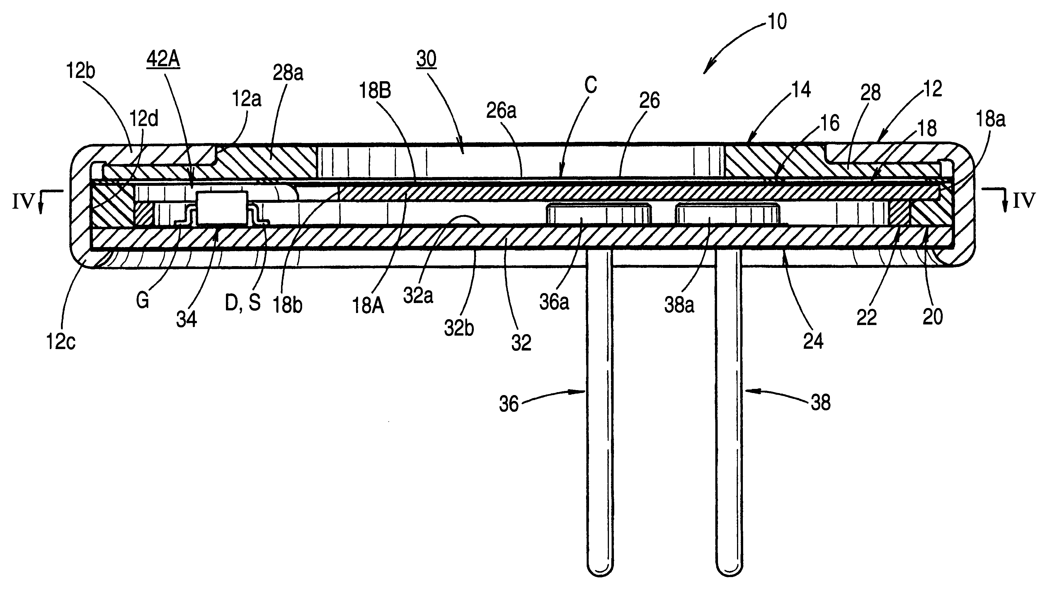
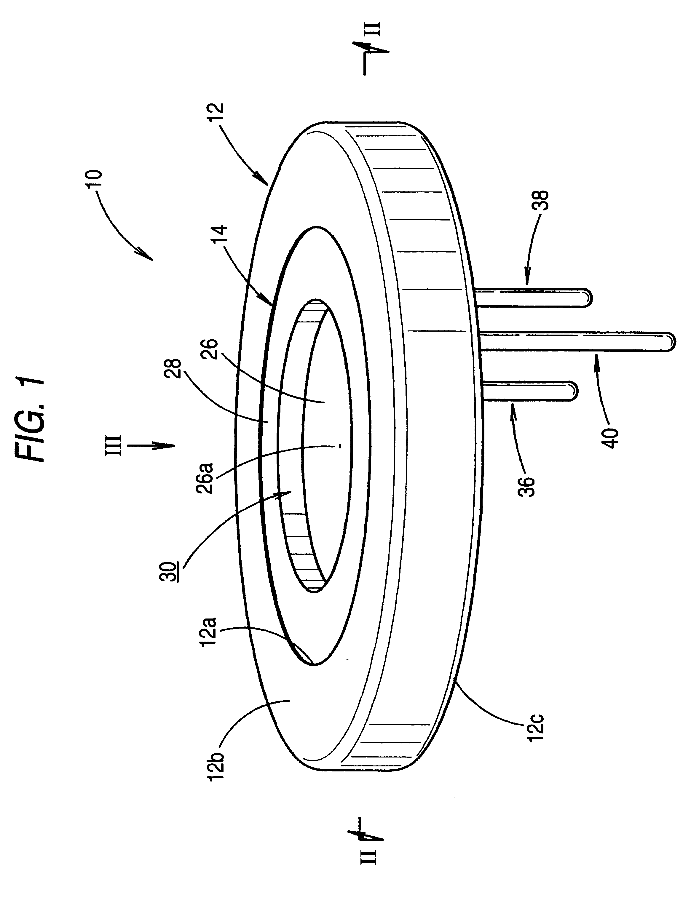
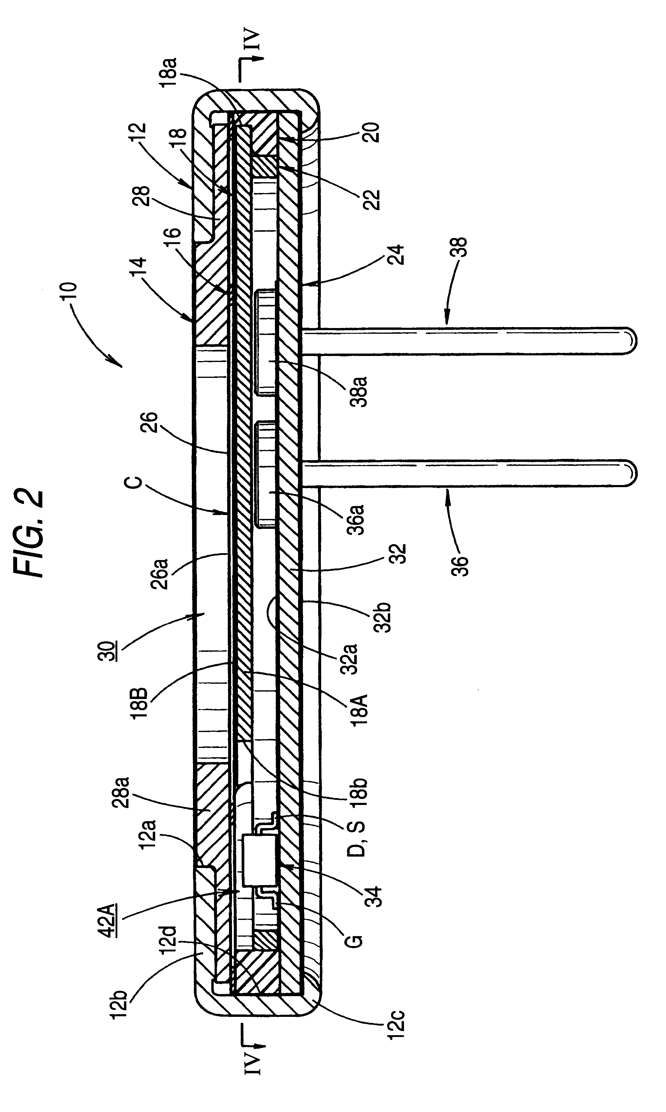
FIG. 1 is a perspective view showing a capacitor microphone disposed facing upward according to an embodiment of the invention. FIG. 2 is a cross-sectional view taken along the line II--II in FIG. 1. FIG. 3 is a view taken in the direction of the arrow III in FIG. 1. FIG. 4 is a cross-sectional view taken along the line IV--IV in FIG. 2. FIG. 5 is an exploded perspective view of the capacitor microphone.

As shown in these drawings, a capacitor microphone 10 according to the invention is an electret-type compact microphone having an outside diameter of about 9 mm. Accommodated are a diaphragm subassembly 14, a spacer 16, a back plate 18, an insulating bush 20, an electrically conductive ring 22, and a junction field-effect transistor (JFET) board 24 (substrate) in the described order in a low-height hollow cylindrical case 12.

The case 12 is a metallic member, fo...


PUM

PropertyMeasurementUnit
diameteraaaaaaaaaa
diameteraaaaaaaaaa
thicknessaaaaaaaaaa

Abstract

A capacitor microphone includes a case having an end wall defining an opening for a sound hole, a capacitor portion comprising a diaphragm, a back plate and a spacer, the diaphragm opposing to the back plate via the spacer, the capacitor portion being accommodated in the case in such an manner as the diaphragm is placed on the side of the end wall, and a substrate accommodated in the case farther from the end wall than the capacitor portion, the substrate having an impedance conversion element mounted on a surface thereof facing the capacitor portion. A communicating opening is provided around the back plate in a position opposing to the impedance conversion element for communicating spaces on the front and back sides of the back plate. The communicating opening has a larger area than that of the top of the impedance conversion element to allow the spaces on both sides of the back plate to communicate with each other. It is possible to ensure that the impedance element and the back plate do not interfere with each other.

Description

1. Field of the InventionThe present invention relates to an electret-type capacitor microphone, and more particularly to a structure of a thin electret-type capacitor microphone.2. Description of the Related ArtConventionally, an electret-type capacitor microphone is known as a type of microphone.As disclosed in, for example, Japanese Utility Model Registration No. 2587682, this electret-type capacitor microphone is arranged such that a capacitor portion and a substrate are accommodated in a hollow cylindrical case whose one end has an end face wall defining an opening for a sound hole and whose other end is open. The capacitor portion is formed by a diaphragm and a back plate opposing to each other with a spacer placed therebetween and a substrate has an impedance conversion element (active element) mounted thereon for converting a change of the electrostatic capacity of the capacitor portion into electric impedance.As disclosed in the aforementioned publication as well, the arran...

Claims


Application Information

Patent Timeline
Patent Type & Authority Patents(United States)
IPC IPC(8): H04R19/00H04R19/01H01G7/02
CPCH04R19/016Y10T29/43
Inventor ITO, MOTOAKIIMAHORI, YOSHIO
Owner STAR MICRONICS
Why Eureka
Try Eureka