Valve attached to fuel tank

a technology of valves and fuel tanks, applied in the direction of valve housings, functional valve types, machines/engines, etc., can solve the problems of liquid fuel flowing into the evaporator opening, affecting the usual adsorption action of activated carbon for vaporized fuel, and affecting the normal adsorption of liquid fuel for vaporized fuel, so as to avoid the effect of affecting the adsorption of liquid fuel

Inactive Publication Date: 2004-01-20
TOYODA GOSEI CO LTD
View PDF7 Cites 32 Cited by
  • Summary
  • Abstract
  • Description
  • Claims
  • Application Information

AI Technical Summary

Problems solved by technology

However, since the liquid surface of the fuel moves up and down, there might be a fear that the liquid fuel flows in into the evaporator opening.
Accordingly, there might arise a fear that the liquid fuel hinders the usual adsoprtion action of the activated carbon for the vaporized fuel.
At this moment, there might be a fear that the fuel and the fuel vapor, held in the fuel tank, flows inversely back to the fuel supply opening.
However, the above-described conventional liquid-fuel flow-out inhibition valve is associated with the following problems.
Moreover, even when only one of the plurality of claws disengages, the swinging of the case might occur so that there might be a fear that the other claws disengage one after another successively.
Accordingly, because of the swelling of the component members, there might arise a fear that the engagement claws are all the more likely to disengage.
However, since the claw engagement is not good inherently in terms of the liquid-proof ability, there might arise a fear that the liquid fuel flows out through the space between the case and the cover.
Namely, it is necessary to give a liquid-proof ability to the space between the case and the cover to a certain extent or more, but it is necessary to give an excessive liquid-proof ability thereto to such an extent that an O ring is disposed therein.
Moreover, a process for assembling the O ring is required, and consequently the manufacturing cost of the liquid-fuel flow-out inhibition valve goes up.
However, the arrangements additionally require manufacturing steps for processing the outer peripheral surface of the case and the inner peripheral surface of the cover, and consequently the manufacturing cost increases.
In addition, because of the complexity of the configurations, the arrangements cannot be applied to small-sized liquid-fuel flow-out inhibition valve.
As a result, the conventional inlet check valve might have a problem that it is inferior in terms of the bondability.
Thus, the conventional inlet check valve suffers from a problem that the number of component parts is large.
Namely, the conventional inlet check valve is associated with problems similar to those of the conventional liquid-fuel flow-out inhibition valve.
Namely, since the case is placed in a manner immersed into a liquid fuel, there may be a fear that the case swells.
When the case swells, as set forth above, there may arise a fear that the case falls off from the cover.
While, regarding the cover, the issue is the fuel permeability.
Moreover, the cover might be subjected to mechanical shocks because of vibrations, and so on, which are transmitted from the other instruments, and the like, boarded on an automobile, etc.
Here, the cover is formed of a polyamide, there arises an issue of the bondability to a fuel tank.
However, the polyethylene and the polyamide exhibit extremely poor bondabilities to each other.

Method used


Image

  • Valve attached to fuel tank
  • Valve attached to fuel tank
  • Valve attached to fuel tank

Examples


example no.1

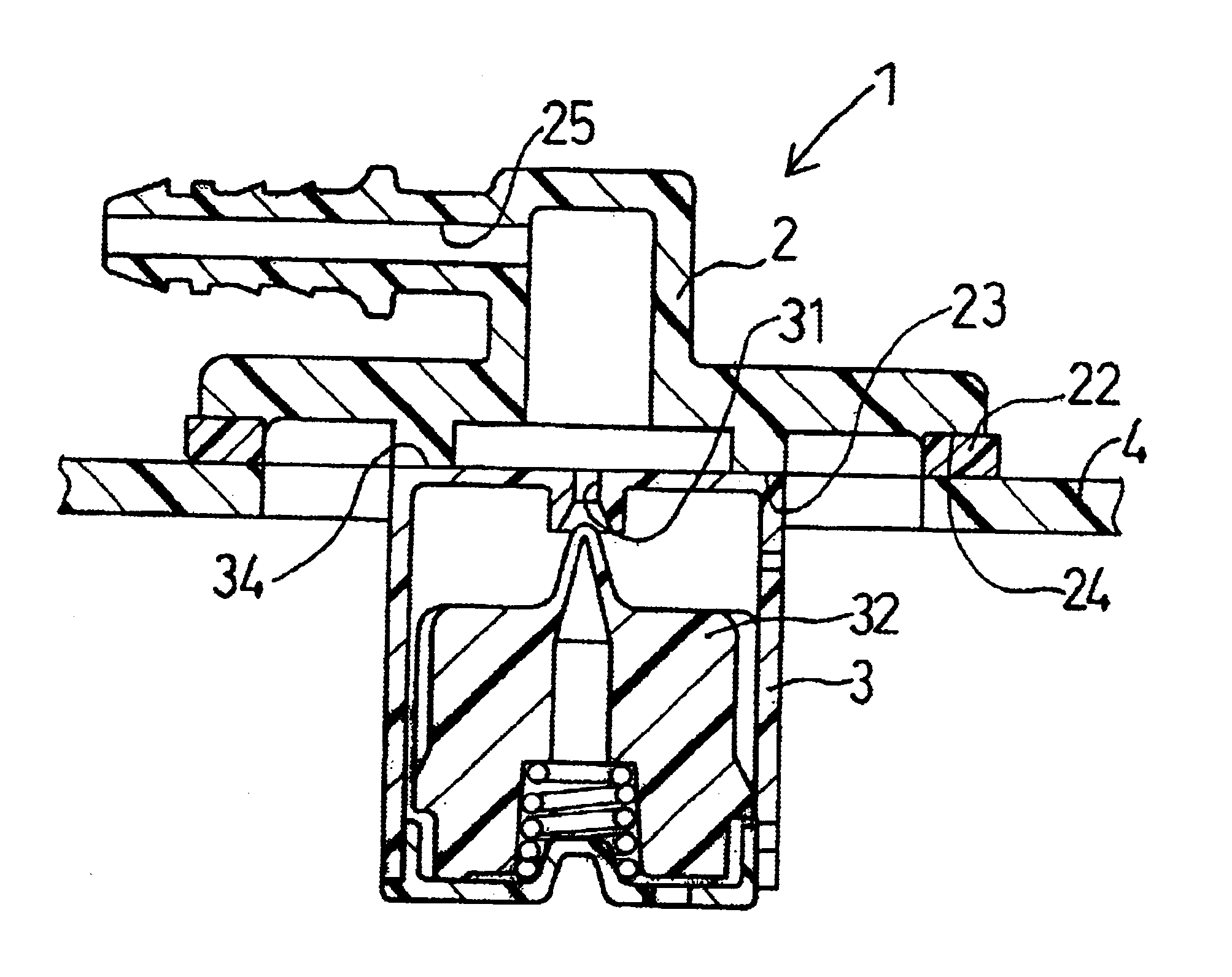
Example No. 1 embodies a valve attached to a fuel tank according to the present invention as a liquid-fuel flow-out inhibition valve.

As illustrated in FIG. 1, a liquid-fuel flow-out inhibition valve 1 of Example No. 1 comprises a cover 2 and a case 3. The cover 2 includes a connecting surface 24, which is to be bonded with a fuel tank 4 and which has a connector portion 22, and a flow-out passage 25, which is disposed therein. The case 3 includes an evaporator opening 31, which is disposed at the central portion in the upper surface, and a floating valve 32, which is disposed therein. Moreover, a female screw 20 is formed in an opening-end inner peripheral surface of the cover 2, and a male screw 30 is formed on an outer peripheral surface of the case 3, respectively.

In Example No. 1, the cover 2 is formed of a polyamide. The connector portion 22 of the cover 2 is formed of an adhesive polyethylene. The case 3 is formed of a polyoxymethylene. The fuel tank 4 is formed of a high-dens...

example no.2

EXAMPLE NO. 2

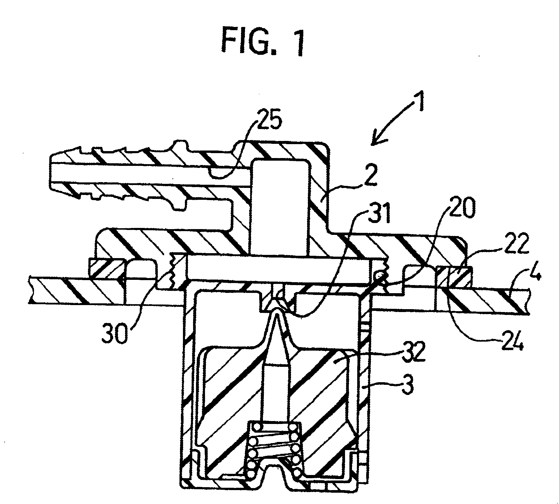
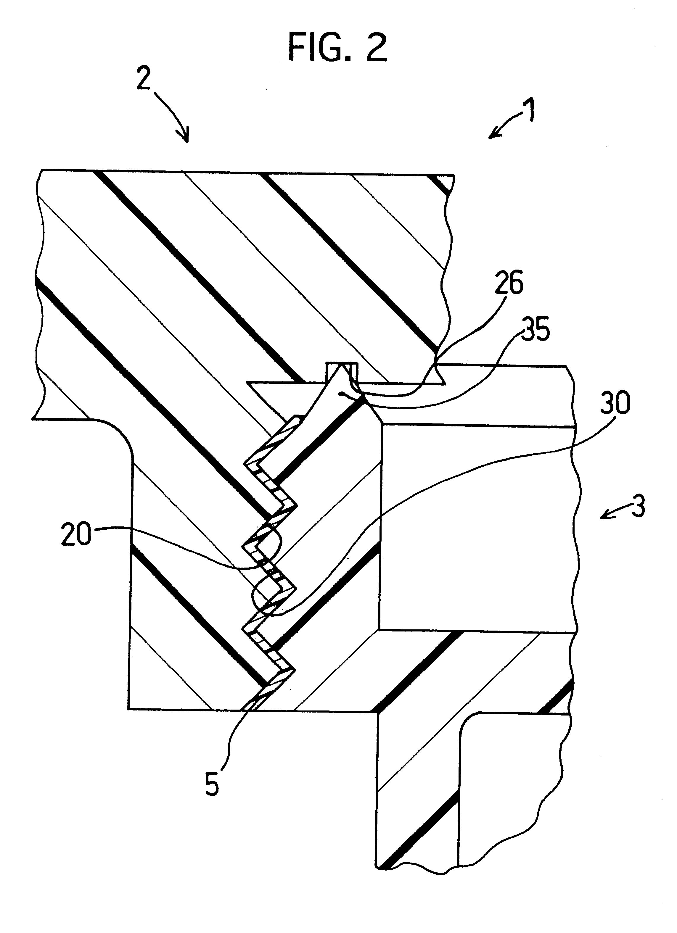
Similarly to Example No. 1, Example No. 2 also embodies a valve attached to a fuel tank according to the present invention as a liquid-fuel flow-out inhibition valve.

Similarly to Example No. 1 illustrated in FIG. 1, a liquid-fuel flow-out inhibition valve 1 of Example No. 2 comprises a cover 2 and a case 3. The cover 2 includes a connecting surface 24, which is to be bonded with a fuel tank 4 and which has a connector portion 22, and a flow-out passage 25, which is disposed therein. The case 3 includes an evaporator opening 31, which is disposed at the central portion in the upper surface, and a floating valve 32, which is disposed therein. Moreover, a female screw 20 is formed in an opening-end inner peripheral surface of the cover 2, and a male screw 30 is formed on an outer peripheral surface of the case 3, respectively.

As illustrated in FIG. 2, an enlarged cross-sectional view of the liquid-fuel flow-out inhibition valve 1 of Example No. 2, the liquid-fuel flow-out ...

example no.3

EXAMPLE NO. 3

Similarly to Example No. 1, Example No. 3 also embodies a valve attached to a fuel tank according to the present invention as a liquid-fuel flow-out inhibition valve.

As illustrated in FIG. 3, a liquid-fuel flow-out inhibition valve 1 of Example No. 3 comprises a cover 2 and a case 3. The cover 2 includes a connecting surface 24, which is to be bonded with a fuel tank 4 and which has a connector portion 22, and a flow-out passage 25, which is disposed therein. The case 3 includes an evaporator opening 31, which is disposed at the central portion in the upper surface, and a floating valve 32, which is disposed therein. Moreover, a male screw 21 is formed in an opening-end outer peripheral surface of the cover 2, and a female screw 31 is formed on an inner peripheral surface of a cylinder-shaped extended portion of the case 3, respectively.

Similarly to Example No. 1 described above, in Example No. 3 as well, the cover 2, the case 3 and the floating valve 32 are produced fi...


PUM


Abstract

Disclosed is a valve being attached to a fuel tank, the valve permitting a vaporized fuel to flow out and inhibiting a liquid fuel from flowing out. The valve includes a cover and a case. For example, the cover is bonded to an upper portion of a fuel tank, is independent of the fuel tank, and includes a connecting surface to be connected to the fuel tank and a flow-out passage in which a vaporized fuel flows out. The connecting surface has a connector portion formed of a resin exhibiting a good bondability to the fuel tank. The case is screwed to the cover, and includes an evaporator opening and a floating valve. The evaporator opening communicates with the flow-out passage. The floating valve opens or closes the evaporator opening.

Description

1. Field of the InventionThe present invention relates to a valve attached to a fuel tank, which is disposed in a fuel tank of vehicles, such as automobiles, and the like.2. Description of the Related ArtIn a fuel tank of an automobile, there is disposed a valve attached to the fuel tank, such as a liquid-fuel flowing-out inhibition valve, an inlet check valve, etc.Among these valves attached to a fuel tank, the liquid-fuel flowing-out inhibition valve inhibits a liquid fuel from flowing out into a vaporized fuel circulation system. Namely, adjacent to a fuel tank of an automobile, there is disposed a vaporized fuel circulation system, which is referred to as an evaporator circuit. The evaporator circuit introduces a vaporized fuel from a fuel tank into an outside canister, and stores it by adsorbing it on an activated carbon, or the like, thereby inhibiting the increment of the internal pressure, which results from the increment of the vapor pressure, in the fuel tank. The canister...

Claims


Application Information

Patent Timeline
Patent Type & Authority Patents(United States)
IPC IPC(8): B60K15/04B60K15/03B60K15/035F16K24/00F16K24/04B60K15/077F02M25/08F02M37/00F16K27/00F16K27/02
CPCB60K15/03519B60K15/04F16K24/044B60K2015/03447Y10T137/86372Y10T137/3099Y10T137/0874
Inventor AOKI, TOMOHIDEKITO, HIROAKINISHI, HIROSHIKANEKO, KENICHIRONAKAGAWA, MASAYUKIANDO, MASAHIRO
Owner TOYODA GOSEI CO LTD
Why Eureka
Try Eureka