Redox flow battery and method of operating it

a flow battery and redox technology, applied in the field of electrochemical reactors, can solve the problems of reducing affecting the overall efficiency of the charging and discharging process, and severe corrosion phenomena on conductive parts

Inactive Publication Date: 2004-02-17
SQUIRREL HLDG
View PDF9 Cites 116 Cited by
  • Summary
  • Abstract
  • Description
  • Claims
  • Application Information

AI Technical Summary

Benefits of technology

Vis-a-vis this state of the art, it has now been found that by realizing or installing check valve liquid vein interrupters in each compartment of the battery the above discussed phenomenon of slow discharge of the retained volumes of electrolytes during long

Problems solved by technology

The parallel flow of the two electrolytes through the respective flow chambers poses serious problems in terms of minimization of so-called stray or by-pass electric currents in uninterrupted liquid veins of electrolyte, due to the fact that the electrolyte present in the manifolds offer innumerable paths for these by-pass or stray currents, driven by mutual voltage differences existing among the various bipolar elements functioning in electrical series between the two end electrodes on which the full battery voltage difference insists.
By-pass or stray currents decrement the energy efficiency of the conversion system, but more seriously they cause severe corrosion phenomena on conductive parts (e.g.: carbon) because of abnormally high half-cell voltages at the conductor surface.
By-pass currents lower the overall efficiency of the charging and discharging processes because by-pass currents represent parasitic discharge

Method used


Image

  • Redox flow battery and method of operating it
  • Redox flow battery and method of operating it
  • Redox flow battery and method of operating it

Examples


example

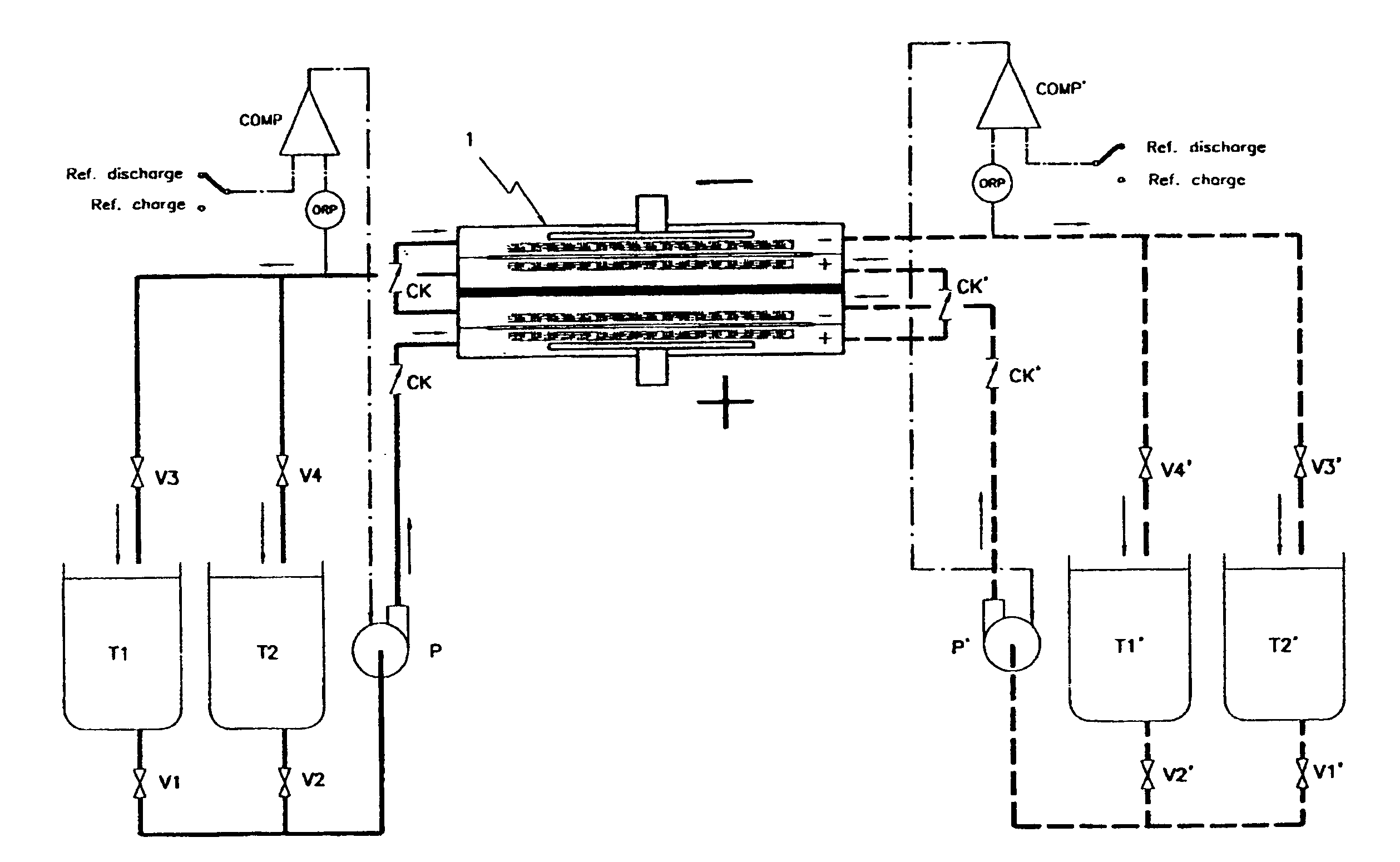
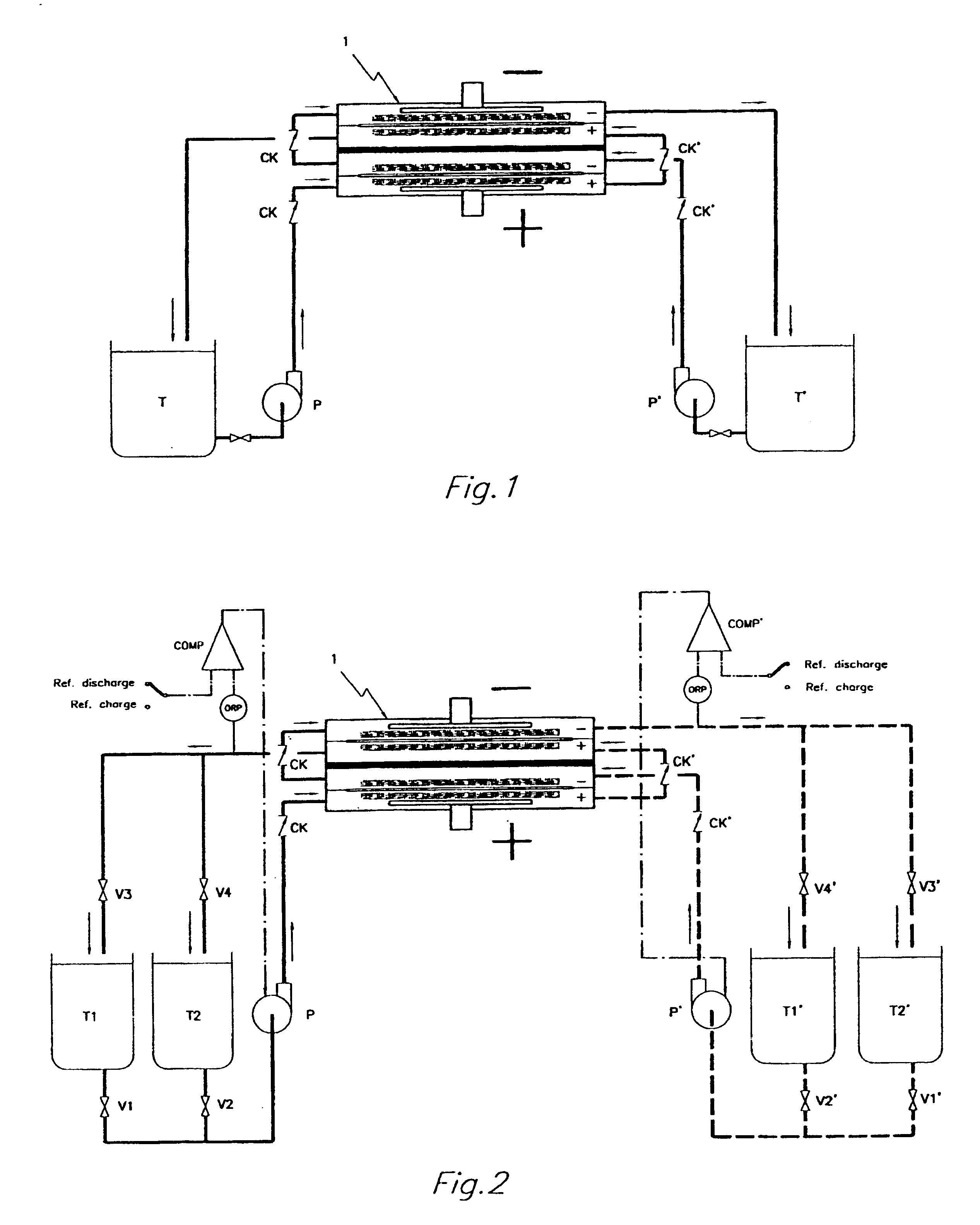
An all vanadium redox flow battery system according to a scheme as the one depicted in FIG. 2 and employing a battery stack composed of twelve cells in electrical series, each having carbon felt electrodes of 18.times.18 cm separated with a cation exchange Nafion.RTM. membrane, manufactured by Du Pont de Nemours, was considered fully charged when attaining a concentration of V.sup.+5 in the positively charged sulfuric acid electrolyte and a concentration of V.sup.+2 in the negatively charged sulfuric acid electrolyte above 90% molar of the total amount of vanadium dissolved in the sulfuric acid electrolyte.

The battery stack was first assembled without implementing any check valve in the inlet and outlet ports of the electrode compartments.

After charging it, the system has been left idle by stopping the pumps and opening the electric circuit.

The battery voltage at the moment of stopping the pumps and opening the circuit was of 17.1 V, but notwithstanding the absence of any electrical...


PUM


Abstract

By realizing or installing check valve liquid vein interrupters in each compartment of the battery the phenomenon of slow discharge of the retained volumes of electrolytes during long periods of inactivity of a redox flow battery, with the electrolyte pumps stopped altogether, can be practically eliminated with the effect that the battery is perfectly ready to deliver electric power immediately upon request even after prolonged periods of inactivity. Moreover, the presence of liquid vein interrupters on each compartment in either an outlet or an inlet port substantially preventing by-pass current during a not pumping phase, permits to increase the by pumping the electrolytes through the compartments of a battery stack intermittently, in other words in a pulsed manner, with a certain duty-cycle. Relatively brief pumping phases at relatively high flow rate alternated to phases of not pumping provide for a volumetrically adequate refreshing of the electrolytes present in the battery compartments and contrast the formation of gradients in the bodies of electrolyte.

Description

1. Field of the InventionThis invention relates generally to electrochemical reactors for conducting reduction and oxidation reactions in respective positive and negative liquid electrolytes, without gas evolution at the electrodes. More specifically, the invention relates to the operation of a membrane-separated, bipolar multicell electrochemical reactor implementing a redox flow battery system, although it may be useful also for different systems.2. Description of Related ArtRedox flow battery systems are increasingly attracting interest as efficient energy storage systems. Among redox couple candidates, the all vanadium redox system is one of the most preferred.Structurally, the electrochemical reactors that have been proposed for redox flow battery systems, have been derived from the electrochemical reactor structures developed for general electrolysis processes, the only adaptation having concerned the materials employed as electrodes.Generally, the electrochemical reactors use...

Claims


Application Information

Patent Timeline
IPC IPC(8): H01M8/18H01M8/04H01M6/48H01M6/42H01M8/24H01M50/77
CPCH01M8/04119H01M8/04283H01M8/188H01M6/48H01M8/246Y02E60/528Y02E60/50
Inventor ZOCCHI, ANDREA
Owner SQUIRREL HLDG
Why Eureka
Try Eureka