Circuit module and method for mounting the same
a technology of circuit modules and mounting methods, applied in the field of circuit modules mounted, can solve the problems of circuit modules that cannot be lifted and carried by chucking devices, circuit modules cannot be chucked and lifted by chucking devices, and it is difficult to maintain the chucking plate parallel to the surface of multi-layer circuit boards
- Summary
- Abstract
- Description
- Claims
- Application Information
AI Technical Summary
Benefits of technology
Problems solved by technology
Method used
Image
Examples
second embodiment
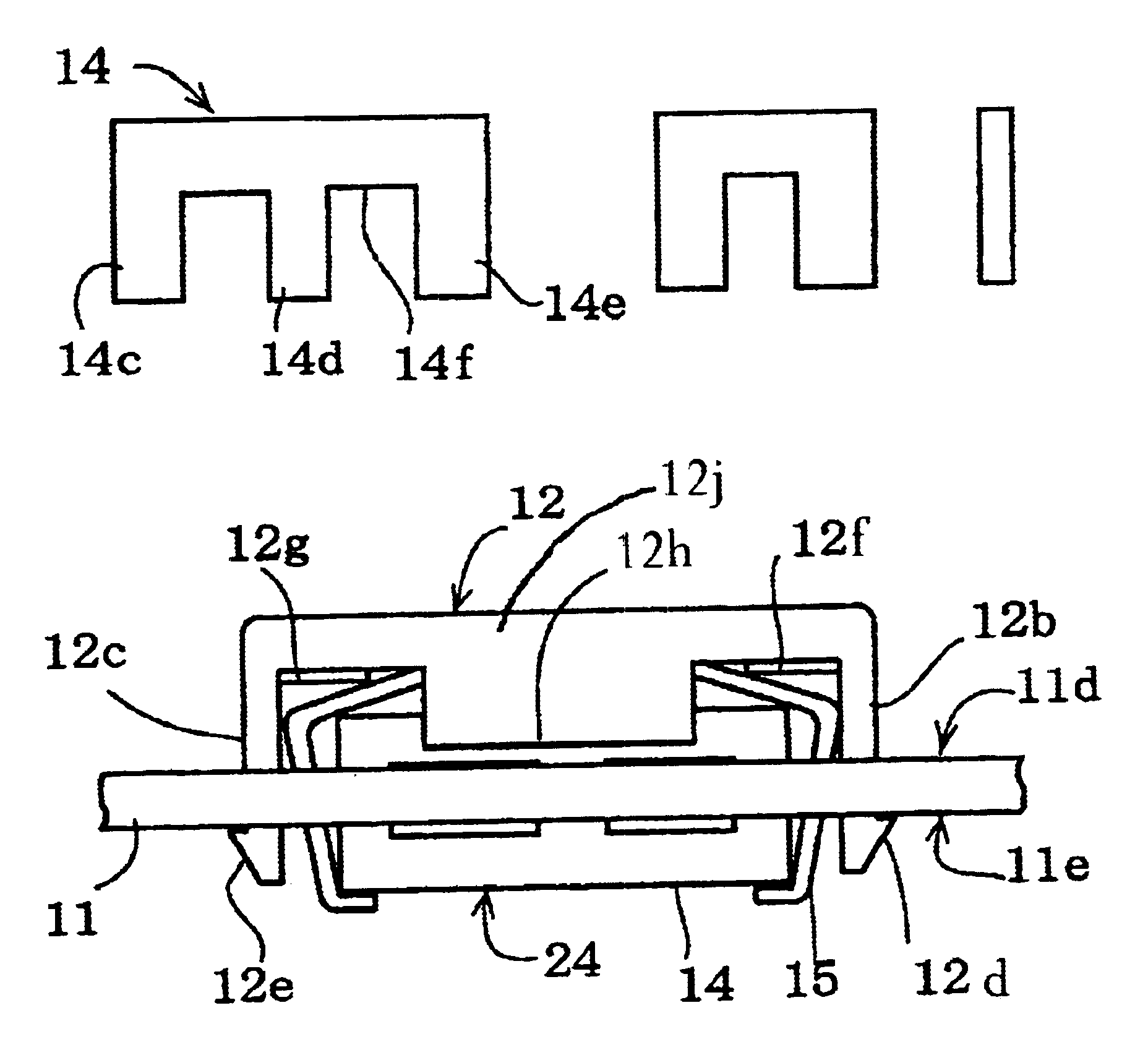
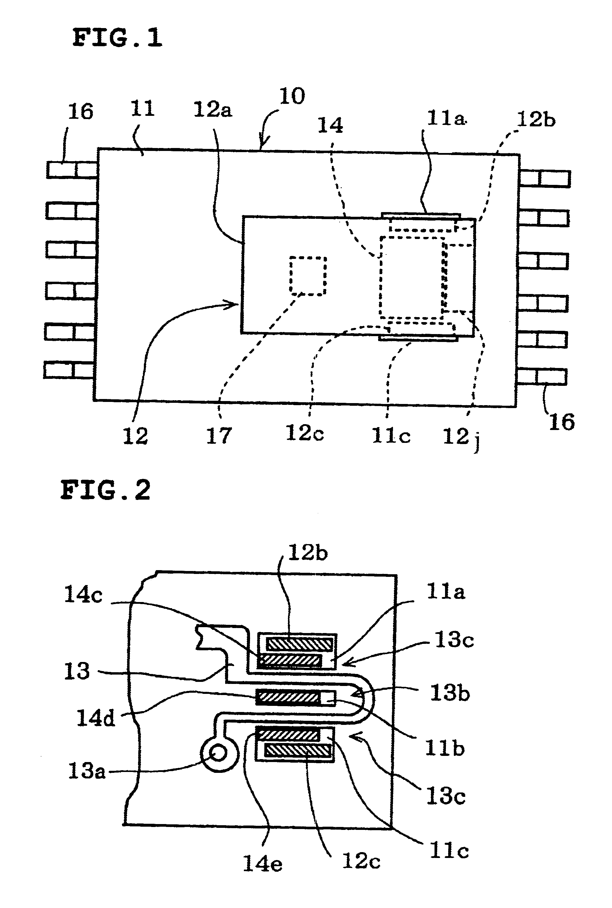
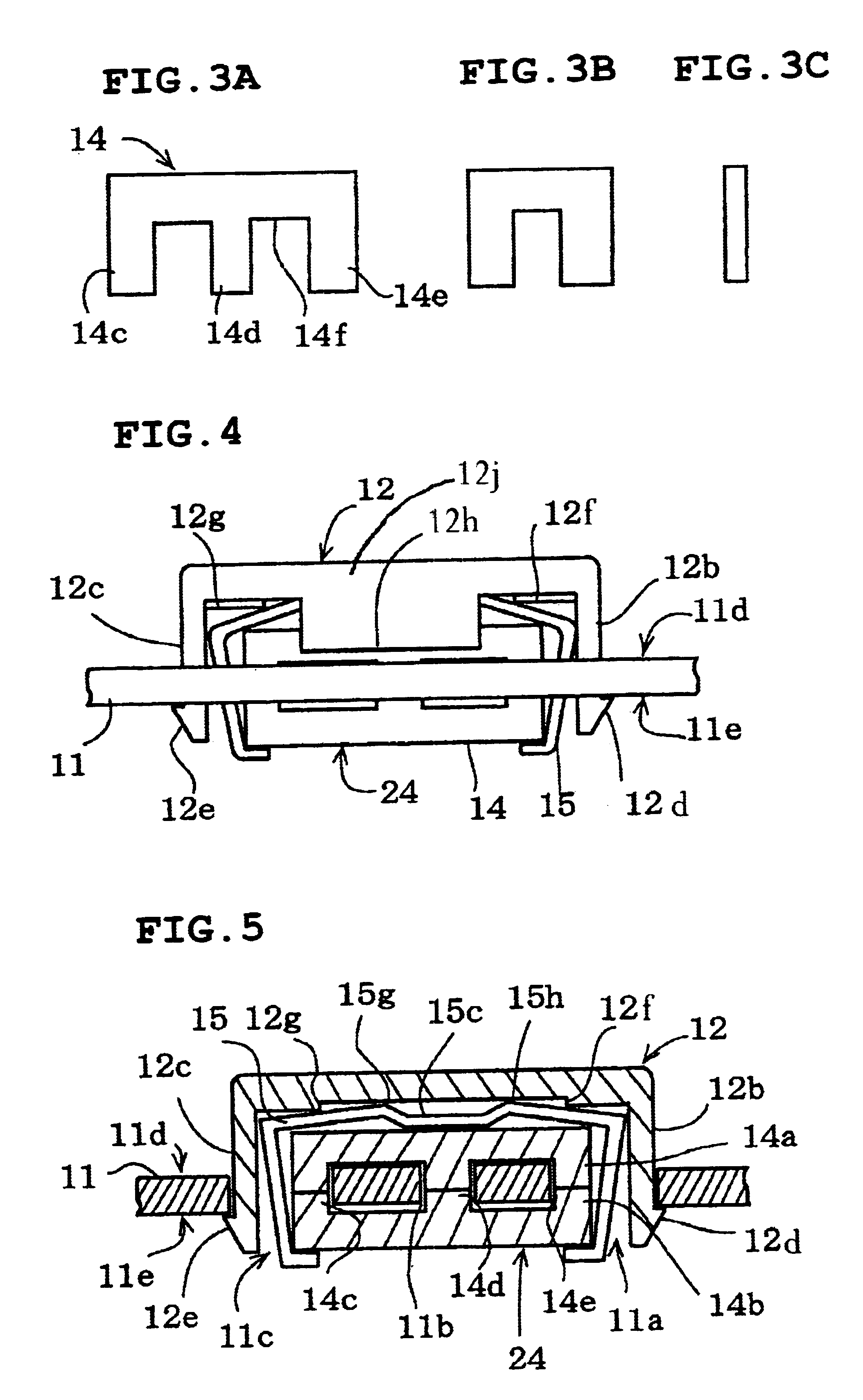
FIG. 8 shows a covering member incorporated in a The covering member 22 has a supporting portion 22c which is provided with two steps 22h and 22j. The supporting portion 22c is also provided with a hook portion 22d at the distal end, in a manner similar to that in FIG. 4. The end portion of the supporting portion 22c is inserted into the through holes 11a formed in the multi-layer circuit board 11. The steps 22h and 22j are pressed against the surface of the multi-layer circuit board 11, and the hook portion 22d is engaged with the edge of the through hole 11a at the bottom surface of the multi-layer circuit board 11. Accordingly, the steps 22h and 22j and the hook portion 22d clamp the multi-layer circuit board 11. With such a construction, the plate portion 22a is maintained parallel to the multi-layer circuit board 11 without utilizing one of the electronic components as a support. In this case, the protrusion 12i as shown in FIG. 6 is not necessary.
third embodiment
FIG. 9 shows a covering member incorporated in a A tongue piece 32d extends from the midsection of the pressing portion shown in FIG. 7. The tongue piece 32d is inserted into the middle through hole 11d along with the middle leg portions 14d of the cores 14, preventing the rattling of the cores.
fourth embodiment
FIG. 11 shows a covering member incorporated in a In contrast to the one shown in FIG. 4, the covering member 42 has supporting portions 42b and 42c which are provided with pressing portions 42e and 42d. The pressing portions 42e and 42d press the cores at the sides thereof, as in the case described above with reference to FIG. 4.
FIG. 12 shows a covering member and a core unit incorporated in another embodiment. The two E cores are fixed to each other by affixing the end surfaces 34a of the leg portions 14c, 14d, and 14e in the through holes 11a, 11b, and 11c with an adhesive, for example, an instantaneously bonding adhesive. Accordingly, the two E cores form a core unit 34. A plate portion 52a of a covering member 52 is provided with a resilient portion 52d which is protruding from the bottom surface. The resilient portion 52d is formed to have a thin arc shape, and has some degree of elasticity so that it can be deformed. Constructions and functions of the supporting portions 52b...
PUM
| Property | Measurement | Unit |
|---|---|---|
| resilient | aaaaa | aaaaa |
| shape | aaaaa | aaaaa |
| conductive | aaaaa | aaaaa |
Abstract
Description
Claims
Application Information
 - R&D
- Intellectual Property
- Life Sciences
- Materials
- Tech Scout
- Unparalleled Data Quality
- Higher Quality Content
- 60% Fewer Hallucinations
Browse by: Latest US Patents, China's latest patents, Technical Efficacy Thesaurus, Application Domain, Technology Topic, Popular Technical Reports.
© 2025 PatSnap. All rights reserved.Legal|Privacy policy|Modern Slavery Act Transparency Statement|Sitemap|About US| Contact US: help@patsnap.com


