Ultrasonic receiving apparatus and ultrasonic imaging apparatus
a technology of ultrasonic imaging and receiving apparatus, applied in ultrasonic/sonic/infrasonic diagnostics, instruments, applications, etc., can solve the problems of reducing affecting and reducing the multiple reflection of ultrasonic waves. , to achieve the effect of increasing the quality of ultrasonic images and reducing the number of ultrasonic waves
- Summary
- Abstract
- Description
- Claims
- Application Information
AI Technical Summary
Benefits of technology
Problems solved by technology
Method used
Image
Examples
first embodiment
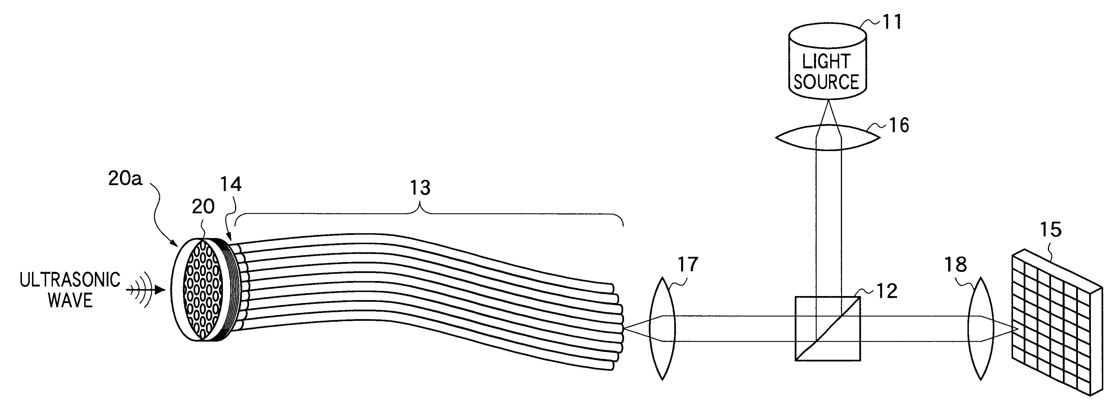
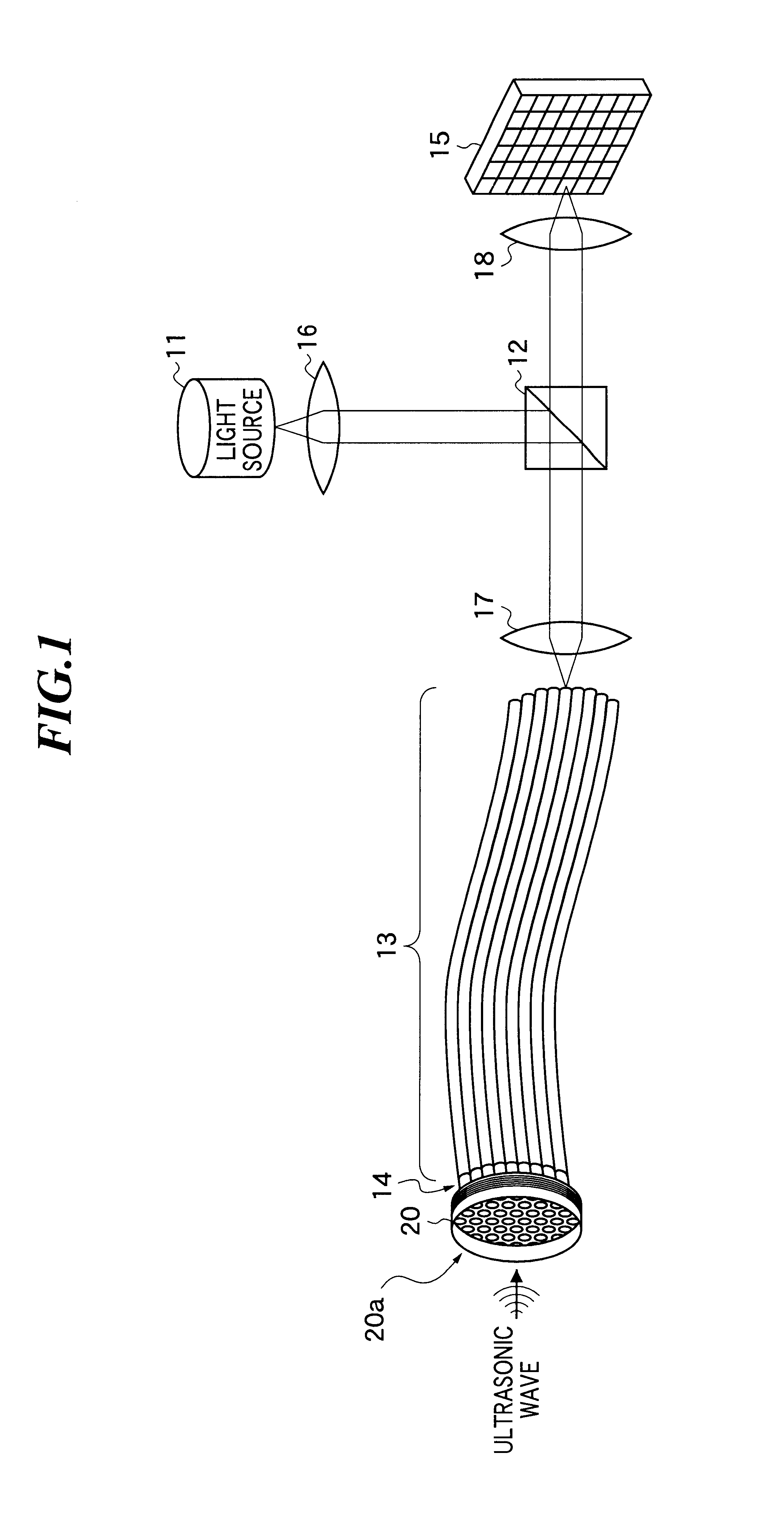
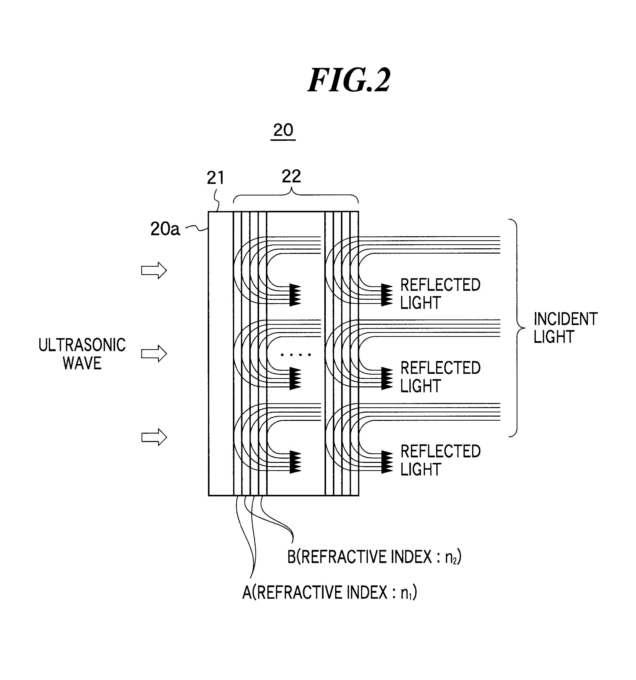
FIG. 1 is a diagram showing ultrasonic receiving apparatus according to the present invention. The ultrasonic receiving apparatus comprises a light source 11, a beam separator 12, an optical transmission path 13, a collimating portion 14, an ultrasonic detecting element 20 for modulating light on the basis of a received ultrasonic wave, a photodetector 15, and focussing systems 16-18.
As for the light source 11, a tunable LD (laser diode) having a predetermined band (for example, 1.55 .mu.m) is used. The beam separator 12 comprises a half mirror, a light circulator, a polarizing beam splitter and so on. The beam separator 12 reflects incident light, which enters from a first direction, to a second direction, and allows the reflected light returned from the second direction to pass through to a third direction which is different from the first direction. In the first embodiment, a half mirror is used as the beam separator 12. The half mirror reflects the incident light in a direction ...
second embodiment
since the multi-layered film is formed directly on the collimator lens, the strength of the connecting portion between the collimator lens and the ultrasonic detecting element is increased. Further, since the reflection of the ultrasonic wave at the connecting portion is further reduced, the ultrasonic wave can be easily released into the fiber portion resulting in an effective prevention of the multiple reflection.
Next, referring to FIG. 6, an ultrasonic receiving apparatus according to a third embodiment of the present invention will be described below. The ultrasonic receiving apparatus as shown in FIG. 6 has a backing portion 50 in place of the optical transmission path 13 and the collimating portion 14 as shown in FIG. 1. The constitution other than the above is the same as that of the first embodiment.
The backing portion 50 includes an optical transmitting portion 51 that transmits the light used for detection and a cover portion 52 for attenuating the ultrasonic wave. As for ...
PUM
 Abstract
Description
Claims
Application Information
 - R&D
- Intellectual Property
- Life Sciences
- Materials
- Tech Scout
- Unparalleled Data Quality
- Higher Quality Content
- 60% Fewer Hallucinations
Browse by: Latest US Patents, China's latest patents, Technical Efficacy Thesaurus, Application Domain, Technology Topic, Popular Technical Reports.
© 2025 PatSnap. All rights reserved.Legal|Privacy policy|Modern Slavery Act Transparency Statement|Sitemap|About US| Contact US: help@patsnap.com


