Pull-out load platform for truck cargo beds

a technology for truck cargo beds and platform, which is applied in the direction of loading/unloading vehicles, transportation items, vehicles with loading gates, etc., can solve the problems of the location is also the most difficult to reach, and the unloading and loading can become even more difficult, so as to reduce the potential for rust and oxidation at the attachment points. , the effect of fast installation

Inactive Publication Date: 2004-03-16
KELLER CYRIL N
View PDF30 Cites 32 Cited by
  • Summary
  • Abstract
  • Description
  • Claims
  • Application Information

AI Technical Summary

Benefits of technology

An advantage of the present invention is that the load platform may be installed quickly and without the need of any tools.
Another advantage of the invention is that the load platform may be completely removed from a cargo bed, leaving the cargo bed free from any intrusive or extraneous frame components or attachments.
Yet another advantage is that the potential for rust and oxidation to occur at attachment points is minimized.
Ad

Problems solved by technology

Unfortunately, this location is also the most difficult to reach.
Unloading and loading can be a problem, especially when the items of cargo are heavy and hard to grip.
This unloading and loading can become even more problematic if the truck has been equipped with a protective cap such as a topper or a tonneau cover.
This limited access means that placing or retrieving an item adjacent the front end of the cargo bed requires that a person engage in a certain amount of gymnastics.
While the aforementioned devices feature a movable platform or bed that is able to extend and retract relative to a cargo bed of a truck, they all suffer from the same drawback in that they are installed on the truck as a permanent or semi-permanent structure.
A related drawback to this type of installation is that tools are required to locate and drill attachment holes, and to attach bolts and nuts.
And, in the case of separate rail supports, pains must be taken to carefully align and center the rails along the cargo bed, because if the rails are not aligned correctly the platform will fail to operate as inte

Method used


Image

  • Pull-out load platform for truck cargo beds
  • Pull-out load platform for truck cargo beds
  • Pull-out load platform for truck cargo beds

Examples


Embodiment Construction

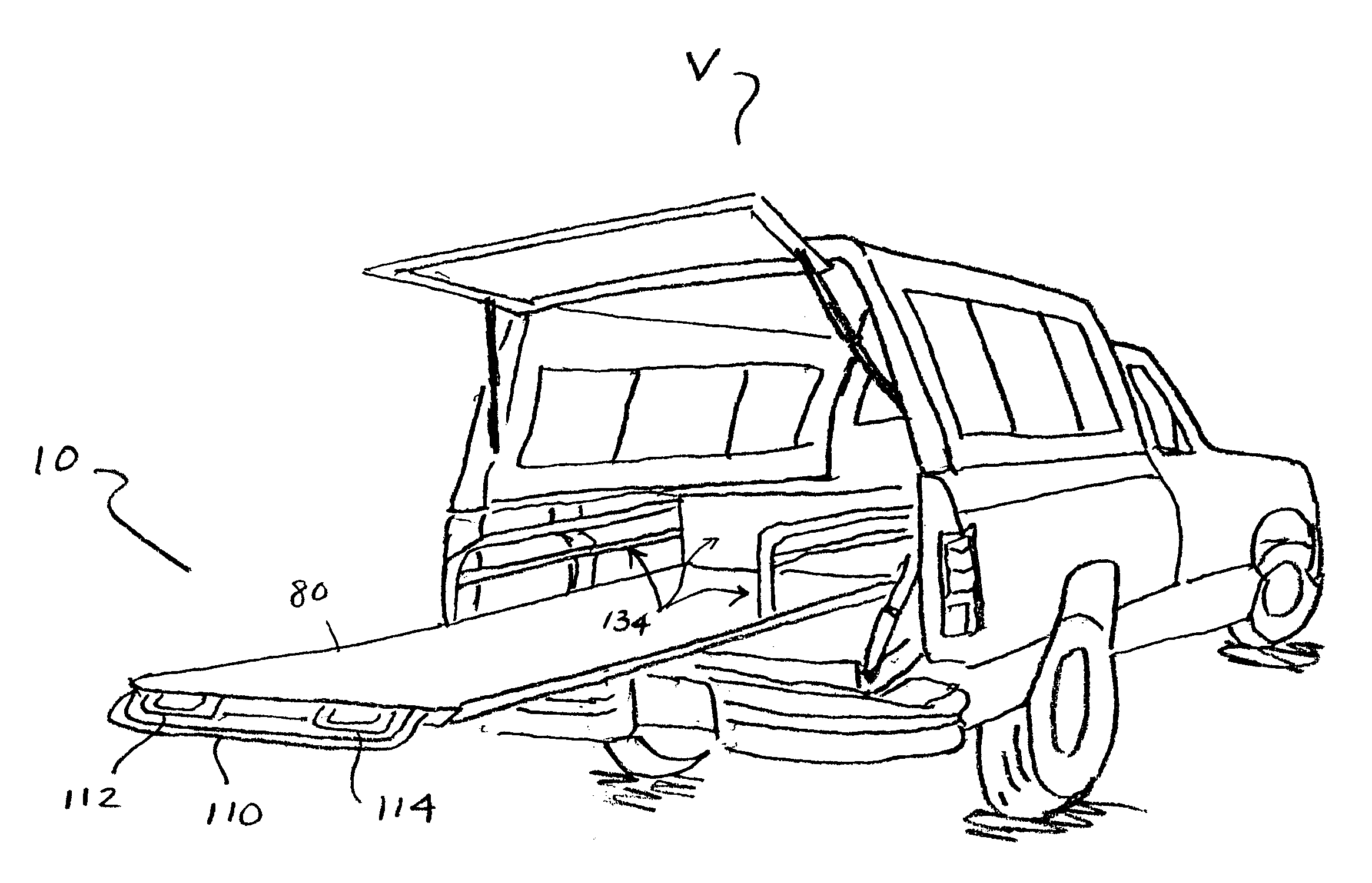
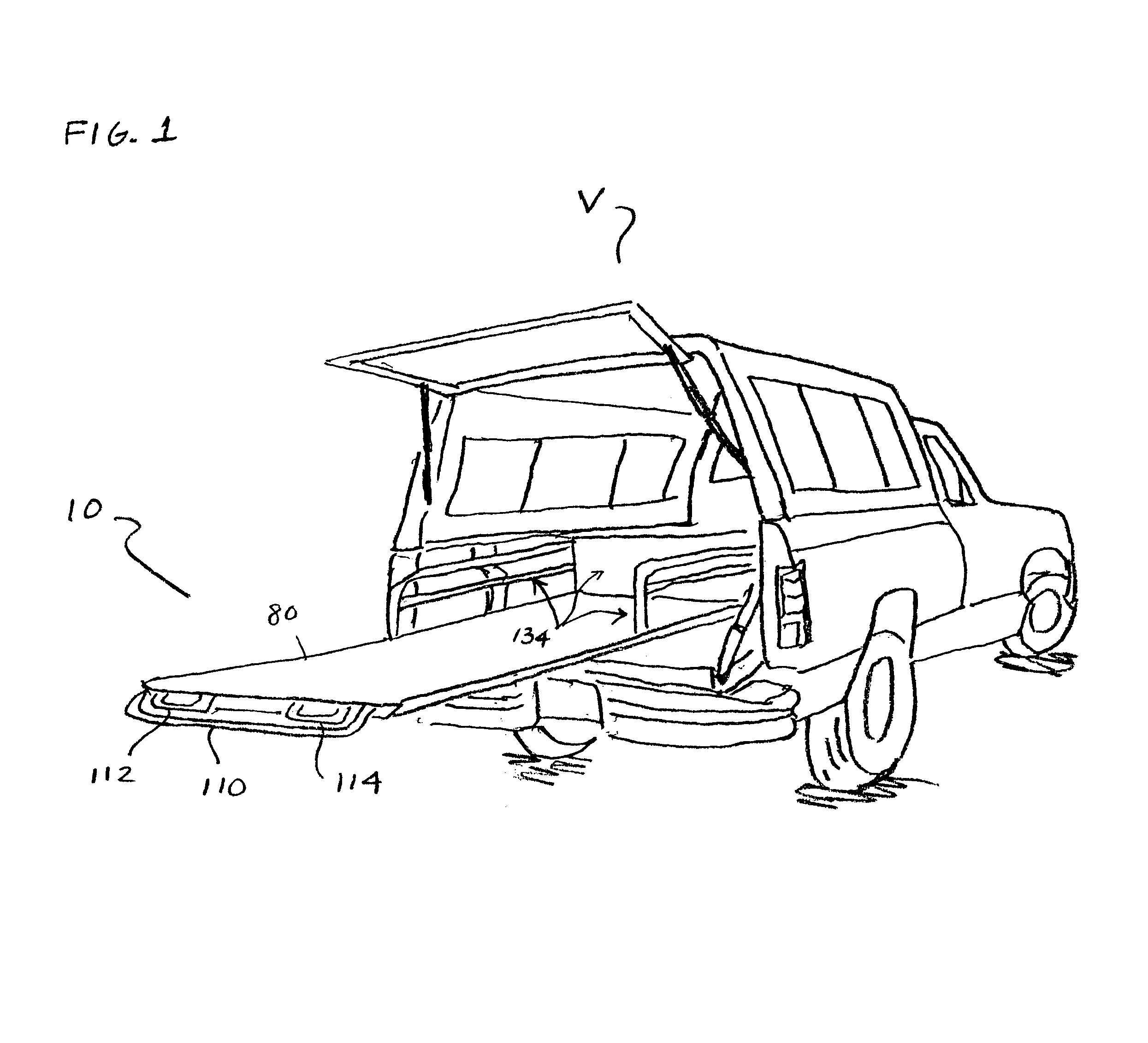
Referring to FIG. 1, a preferred embodiment of the pull-out load platform 10 of the present invention is depicted as it may be used in conjunction with a cargo bed of a vehicle V such as a pickup truck. As shown, a load platform 10 has been installed in the vehicle 10 and the deck 80 has been extended so that its rear end is cantilevered relative to the support structure of the load platform 10, and to the cargo bed and tailgate of the truck. In this extended or access position, cargo that would normally be located near or at the front end of the cargo bed is now located within arm's reach. Thus, a user may load or unload cargo with relative ease, and reduce the of risk injury due to overextension or by crawling into the cargo space. Note that the deck 80 of the load platform 10 is sized so that it has a smaller footprint than the cargo bed of a truck, which enables the tailgate or other closure to operate in a normal fashion.

The deck 80 may be provided with structure 134 (for examp...


PUM


Abstract

A pull-out load platform truck cargo beds. The load platform has a frame with a base, a plurality of outriggers that extend therefrom, and a pair of rails that are aligned with the base. The outriggers and the rails are adjustable and have ends that are configured and arranged to engage surfaces of a truck body in a non-invasive manner, so that when the load platform is installed in a cargo bed of a truck, the base is prevented from moving relative thereto. A deck, onto which cargo may be placed, is operatively connected to the frame and movable relative thereto, preferably in a constrained manner. When the deck is pulled out relative to the frame so that it extends partially beyond the end of the base in a cantilever fashion, the deck is prevented from tipping by the operative connection between the frame and the deck.

Description

FIELD OF THE INVENTIONBACKGROUND OF THE INVENTIONThis invention relates generally to aftermarket truck accessories. More particularly, the present invention relates to a pull-out load platform for truck cargo beds.The popularity of pickup trucks in today's society is undeniable. From rather humble beginnings, they have evolved from a simple, basic, transporter into a sophisticated, stylish and powerful vehicle. Yet, the sine qua non that defines a pickup truck has not changed appreciably over the years. This essential element is the cargo bed.Generally, the safest area in which to place an item of cargo is towards the front and center of the cargo bed, adjacent the cab of a truck. Unfortunately, this location is also the most difficult to reach. Unloading and loading can be a problem, especially when the items of cargo are heavy and hard to grip. Either a person must try to retrieve an item of cargo from the sides of the cargo box, or the person must get into the cargo box to retrie...

Claims


Application Information

Patent Timeline
IPC IPC(8): B60P1/00
CPCB60P1/003
Inventor KELLER, CYRIL N.
Owner KELLER CYRIL N
Why Eureka
Try Eureka