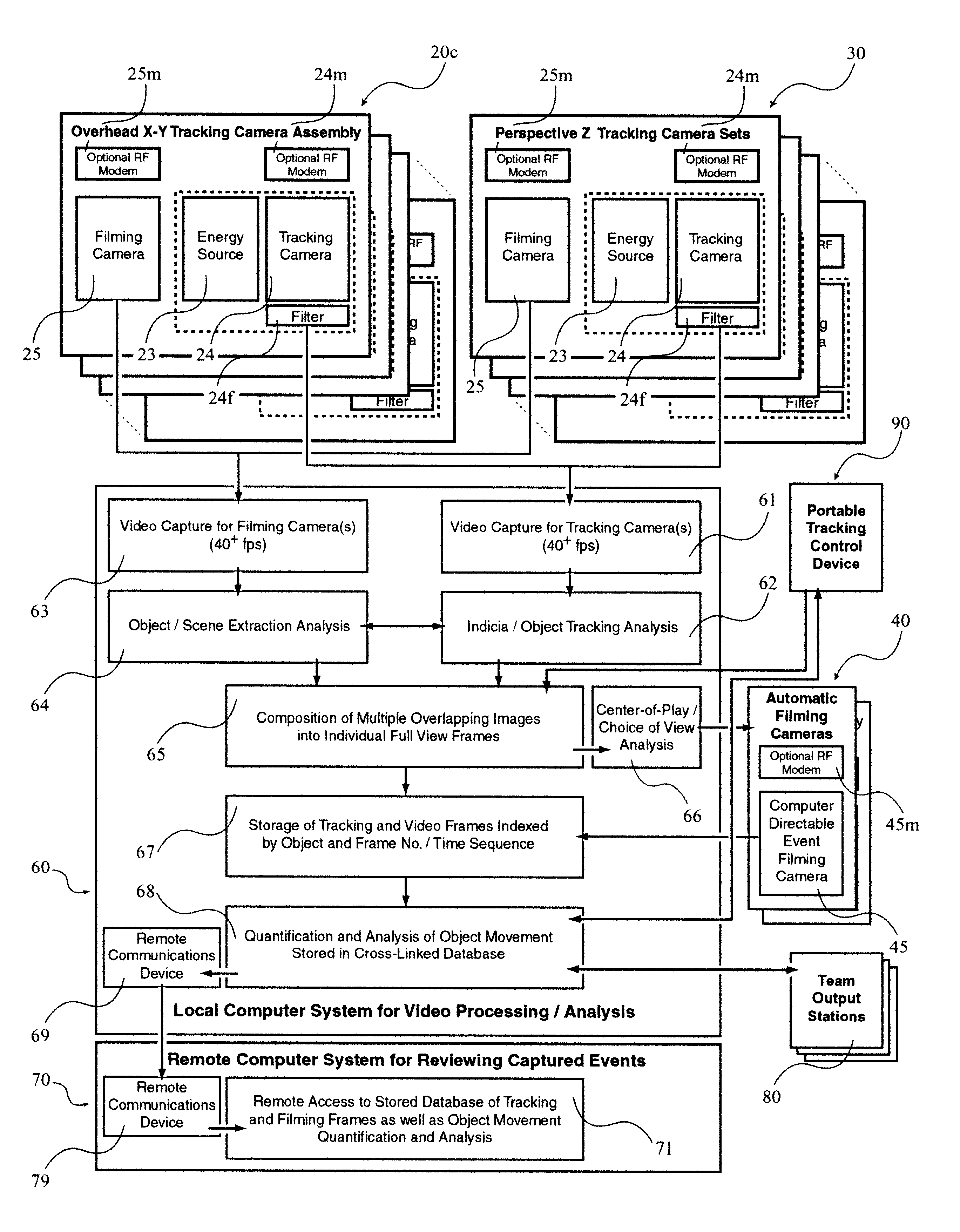
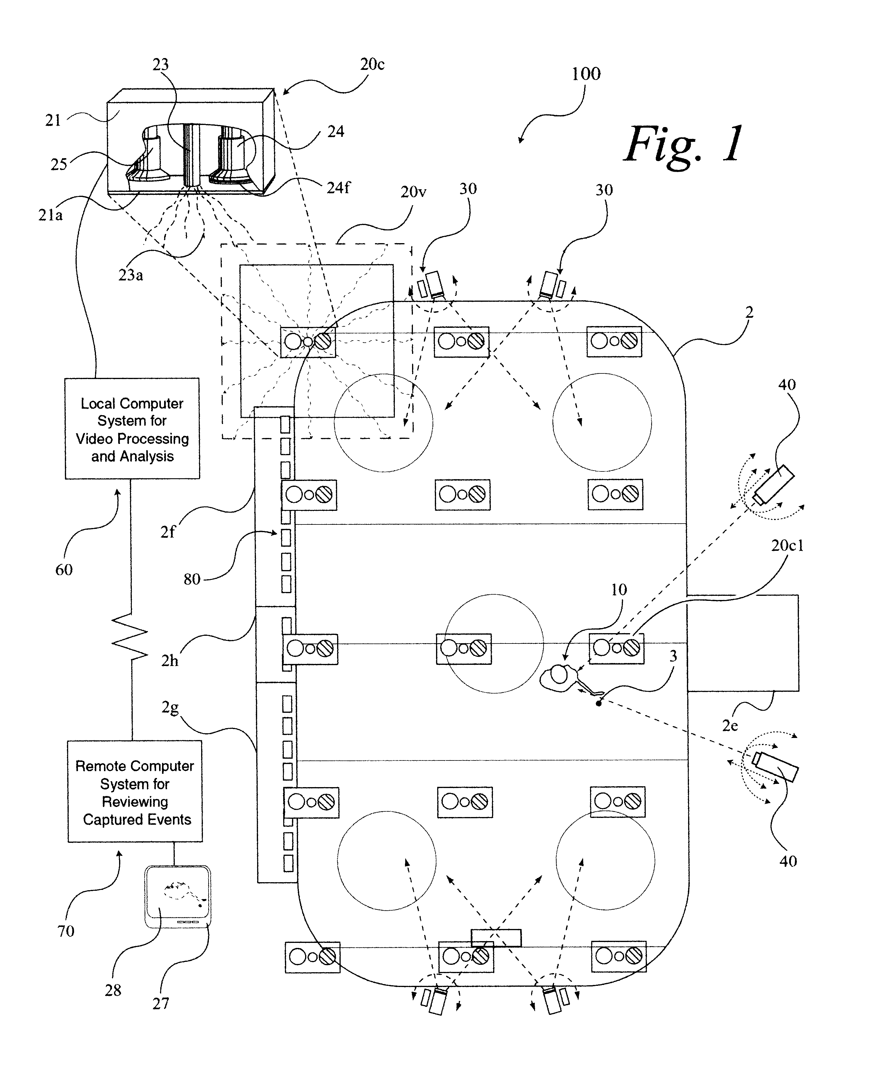
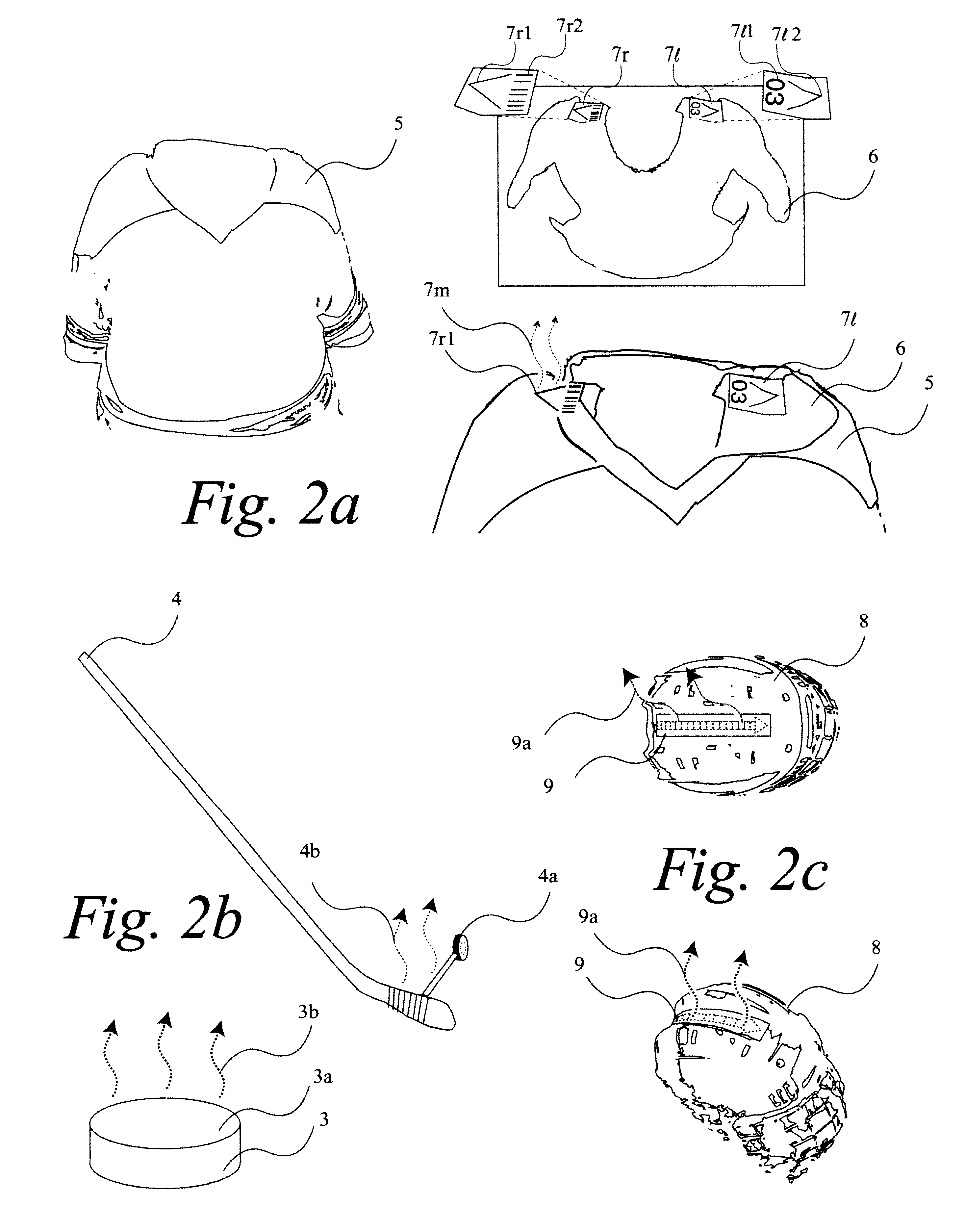
The variability of humans and their clothing as well as the complexity of the backgrounds within which they endeavor has presented a significant challenge to state-of-the-art technology.
However as resolution increasing so does the cost of the camera as well as the accompanying computer
system.
And as time to process increases the ability for these systems to perform real-time operations is impeded.
The inventor had anticipated problems when the individual players would collide or otherwise engage each other and hence merging their individual silhouettes.
Secondly, they proposed attaching electronic tracking devices and employing
triangulation of received signals in order to identify and track individual players.
There are at least four major problems with the Larson patent.
First, the amount of digital
processing required to perform the player extraction in real time greatly exceeds the cost-effective
computer technology of today, let alone 1994.
Secondly, in order to perform this extraction, a greater amount of detail would be necessary which would thereby increase the cost of implementation by requiring more cameras and related computer systems.
And of course the additional detail would only tend to further slow down the responsiveness of the system.
Thirdly, the requirement of one or more operators to initially recognize and then re-identify players is extremely limiting and costly.
This requirement essentially made the patent economically impractical for monitoring non-professional youth sporting events, where the system cost including the ongoing cost of the
human operator would greatly exceed smaller revenue streams.
This approach would also require training and retraining operators, which would also be prohibitive.
Fourthly, the type of
electronics necessary to track players in real time would have to operate at higher frequencies that would also mean that it would be more expensive, providing a further economic drawback.
The fifth major problem is that the system could have a difficult time determining the orientation of the player.
For example, while Larson's invention could detect the direction of an individual's motion, it could not determine if the person was facing forwards or backwards, let alone if the person's head was turning in another direction.
It was pointed out that such systems depended upon
time consuming and error prone statistical calculations that were especially susceptible to misinterpretation when the object changed size within the
field of view or disappeared altogether.
However, there are at least five major problems with Abe's patent.
First, the effectiveness and reliability of this technique is highly dependent upon the lighting conditions initially and over time within the
field of view being tracked.
However, when the lighting conditions are poor to begin with, or worse yet change from frame to frame as might happen with sudden burst of ambient light, the luminance histograms will be subject to considerable error.
Secondly, relying upon color histograms is equally uncertain due partly to the susceptibility of
color detection to lighting conditions, which again may vary from frame to frame, and in part to the potential for object and background blurring when color schemes overlap.
A third problem is that Abe'
s system does not lend itself to tracking multiple objects that may have similar or identical luminance / color information and which may overlap from frame to frame.
This requirement would be even more restrictive when consideration is given to multiple object tracking where the objects may go in and out of the
field of view of temporarily overlap each other.
And finally, a fifth problem is alluded to in the specification where it is expressed as an opportunity of the system to automatically control the pan, tilt and
zoom of a camera.
In Hashima's review of the prior art he lists several existing methods many of which require too many calculations and or have problems with multiple objects and
background image noise.
Secondly, by attempting to determine three dimension information from a single two dimensional image, Hashima is focusing his solution on situations were additional perspective cameras may not be available.
However, if every one of these multiple objects needed to be tracked within the same image, Hashima's invention would not be at optimal performance since at any given time the preferred orientation of camera to object cannot be simultaneously maintained for multiple objects scattered in three dimensions.
Such a device will typically take up more space than a marking or indicia that can be placed on an object and then tracked with a camera.
Furthermore, this device will require power.
Secondly, Lemelson et al.
However, there are many situations when it is desirous to follow the exact and continuous movements of all tracked objects as they move about within a predefined area.
Whereas it is conceivable that this invention could constantly transmit "inquiry signals" for all objects and constantly receive locating
signal responses, it is anticipated that this amount of information would unacceptably limit the movement resolution of the system.
Thirdly, such an electronic based system has no understanding of an object's orientation with respect to it's direction of movement.
Hence, while it is possible to determine the direction a car or person being tracked is moving, it is not shown how the system could determine if that same car or person was facing or turned away from it's current direction of travel.
However, without actually first determining where the object is located, say for instance by attempting to triangulate the sound emitted by the object, the system would have no idea which cameras to activate.
The second limitation is that this system does not attempt to uniquely identify each object that it senses.
Hence, while it is capable of determining a trajectory vector for individual objects, it does not anticipate a need for, nor disclose a method of determining the unique identity of each object as it passes by.
The third limitation deals with the ability to track multiple objects simultaneously within this same field of view.
The forth limitation deals with the systems inability to pick up the object from its background when there is insufficient color and or
luminescence difference between the two.
2--If the
tracking system attempts to reduce
processing time by performing averaging techniques based upon separated color and
luminescence information as does Abe, then accuracy is compromised especially as colors merge between multiple objects and their background or lighting conditions fluctuate substantially between image frames.
Such reduction techniques are further hampered as object size diminishes which essentially reduces the amount of object versus
background information thereby increasing "
noise".
This then implies that each object being tracked must have its own camera thereby greatly reducing the effectiveness of these techniques for tracking either more objects and / or greater fields of view.
However, Hashima faces significant issues when trying to determine three-dimensional information from a single two-dimensional image, which is one of his mandatory requirements.
His
resultant techniques preclude the tracking of multiple fast moving objects over wider fields of view where the object's indicia may at times be blocked from view or at least be at significantly changing perspectives from the tracking camera.
5--All of the video / camera only based techniques such as Larson, Abe, Hashima and Lowery are prone to error if they were to track multiple objects whose paths would intersect and / or collide.
Such operators are cost prohibitive and also limited in their capacity to keep up with multiple fast moving objects in real time.
While, as Larson suggests, it is possible to use passive
electronics to help identify objects once the system determines their identities have been lost, these devices will have their own resolution / speed of response restrictions which are
cost sensitive.
The intervention of any operator is both cost prohibitive and real-time-response limiting.
This technique is inherently limited to objects that make distinguishing sounds.
It is also unable to track multiple objects that might be making similar noises simultaneously within the given field of view.
Such devices limit the range and type of objects that can be tracked based upon the practicality and cost of embedding computing devices.
In systems such as Lemelson's that employ
electronics alone, the wealth of information available from image data is lost.
Furthermore, such systems may be able to track location but cannot track
object orientation, e.g. is the object traveling forwards or backwards.
9--With the exception of Hashima's indicia technique, all of these solutions are still not capturing
object orientation information.
10--All of the video / camera based solutions will have difficulty picking up fast moving objects whose color and or
luminescence information is sufficiently close to that of other tracked objects or the image background no matter what technique is employed.
All non-
video based solutions will give up valuable image information.
Tracking these faster movements, especially given the variability of the human form, challenges the real time performance aspects of the system.
This combination of speed and re-direction presents a difficult tracking problem and is unique in athletics.
This creates a challenge to follow movements with often limited or no image data.
5--The lighting conditions are difficult to work with since the ice surface will create a highly reflective background that could tend to saturate the CCD elements of the camera while the area itself may be subject to sudden bursts of light from either spectator's camera flashes or in-house lighting systems.
This places limitations on luminescence based tracking techniques.
This places limitations on color based tracking techniques.
This challenges any camera-based system since it could greatly reduce
visibility of the players and puck.
Automatically directing a camera that is situated for a perspective view presents a difficult problem for a
machine vision system since it is considerably harder to follow the objects in three dimensions in real time as a perspective view would require.
10--The enclosed
metal and
cement block arena precludes the use of GPS and presents difficulties for the use of passive electronic tracking devices due to the many potential reflections of in-house
triangulation signals.
The players themselves and the nature of the game and its potential for significant high
impact collisions limit the desirability of placing active electronic devices within their equipment.
Since these devices must carry a power source they will in practice take up enough space to present a potential
hazard to the players.
Furthermore, such devices would be extremely cost prohibitive at the local rink level where literally hundreds of children are playing games every week and would each need their own devices or to share devices.
A player's head may be tilted down towards the ice, which is not desirable for prolonged periods of time or if often repeated.
All of this information is important to track but presents problems over and above simply tracking the player as a whole.
13--The number and speed of player changes and collisions is so great that utilizing human intervention to identify and re-identify players would be significantly stressful and error prone, if not practically impossible, especially at the local rink level.


