Methods and apparatus for forming anastomotic sites

Inactive Publication Date: 2004-03-30
AARON V KAPLAN M D
View PDF27 Cites 81 Cited by
  • Summary
  • Abstract
  • Description
  • Claims
  • Application Information

AI Technical Summary

Problems solved by technology

Alternatively, the geometry or contour of the inflated balloon may be complex and present a trough or channel at

Method used


Image

  • Methods and apparatus for forming anastomotic sites
  • Methods and apparatus for forming anastomotic sites
  • Methods and apparatus for forming anastomotic sites

Examples


Embodiment Construction

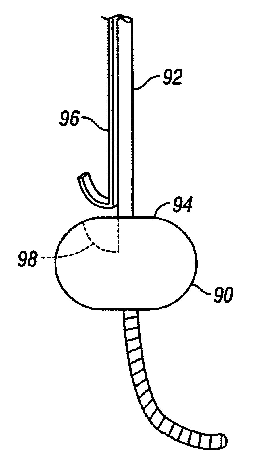
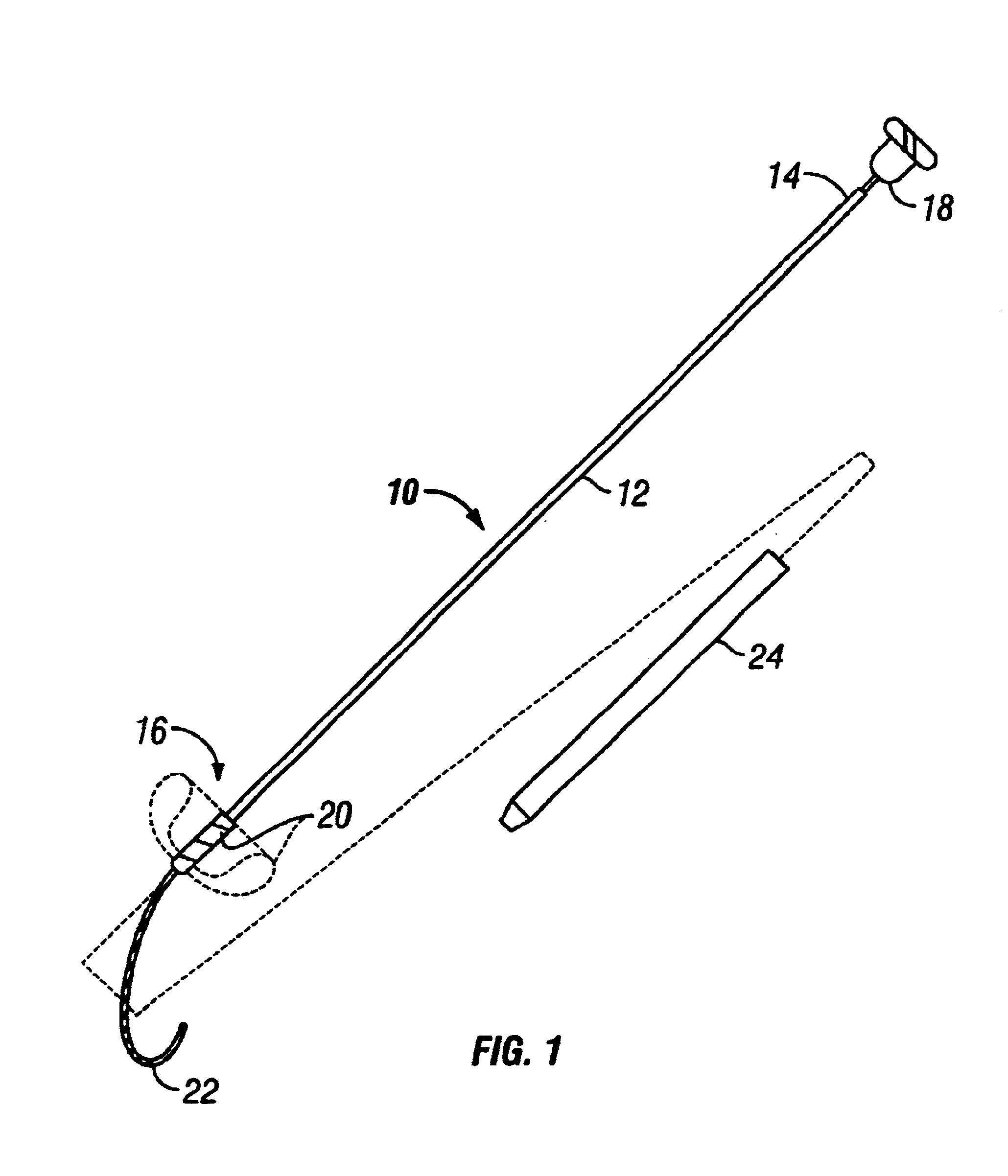
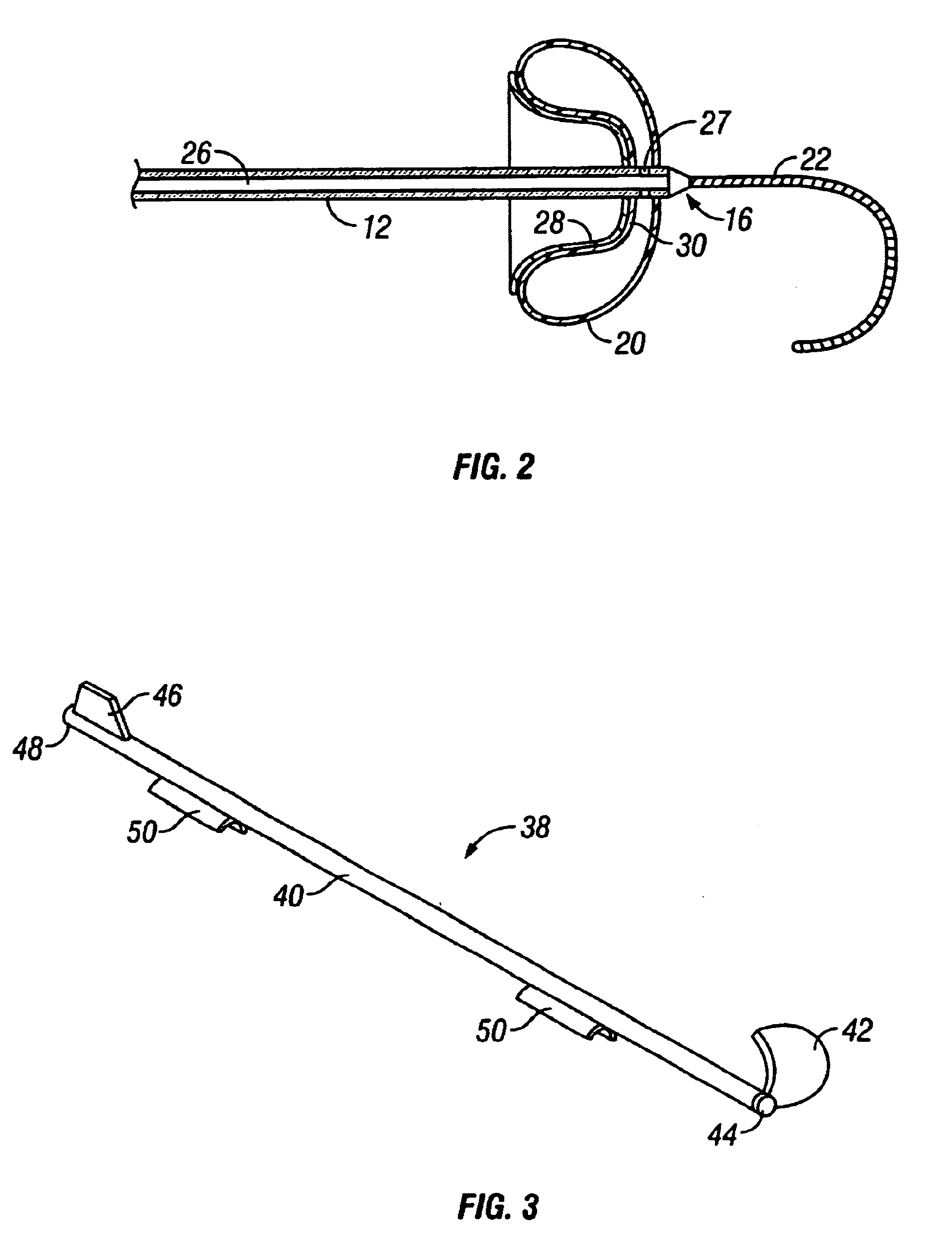
A first exemplary inflatable barrier tool 10 constructed in accordance with the principles of the present invention is illustrated in FIGS. 1 and 2. The inflatable barrier tool 10 comprises a shaft 12 having a proximal end 14 and a distal end 16. The shaft 12 may be formed from a variety of low diameter, medically acceptable tubular materials, such as hypotube. The shaft will usually have a diameter in the range from 0.4 mm to 1.4 mm, and a length in the range from 10 cm to 30 cm. Tool 10 further comprises an inflation of hub 18 which is removably attached to the proximal end 14. An inflatable barrier 20 is attached to the distal end 16 and illustrated in its deflated condition in full line and inflated condition in broken line (in FIG. 1). A guidewire 22 is fixed to the distal end 16 of the shaft 12, and a separate removal sheath 24 is provided. The removal sheath 24 has a central lumen (not shown) which is dimensioned to receive the shaft 12 and balloon 20 in its deflated conditio...


PUM


Abstract

Apparatus and methods are provided for forming a working space on the interior wall of a blood vessel, such as the aorta. The working space is isolated from blood flow and permits creation of an anastomotic hole and subsequent suturing of the hole to form an end-to-side anastomosis, even while the heart is beating. The apparatus comprises tools including inflatable barriers, such as cup-shaped balloons, which engage the inner wall of the blood vessel with minimum trauma and maximum sealing. In a first embodiment, the inflatable barrier is introduced through a penetration at the site of the anastomotic attachment. In a second embodiment, the inflatable barrier is introduced through a second penetration axially spaced-apart from the site of the anastomotic attachment.

Description

1. Field of the InventionThe present relates generally to medical apparatus and methods. More particularly, the present invention relates to methods and apparatus for creating isolated working spaces within the lumen or a blood vessel to facilitate forming end-to-side anastomoses.Coronary artery bypass graft (CABG) surgery remains one of the most common treatment for coronary artery disease in the United States and other developed countries. Vein grafts, typically harvested from the patient's legs are connected to the aorta and then to the coronary arteries beyond diseased regions. This procedure is typically performed with the patient's heart stopped after initiation of cardiopulmonary bypass. Cardiopulmonary bypass and stopping the heart has been associated with stroke as well as heart muscle damage. To reduce these risks, surgeons have developed techniques to perform CABG while the heart is still beating avoiding cardiopulmonary bypass.CABG using beating heart technique is perfor...

Claims


Application Information

Patent Timeline
IPC IPC(8): A61B17/11A61B17/03A61B17/00A61B17/04
CPCA61B17/11A61B17/0057A61B17/0482A61B17/0493A61B2017/00557A61B2017/1107A61B2017/1135
Inventor KAPLAN, AARON V.BAJOR, JORDAN T.
Owner AARON V KAPLAN M D
Why Eureka
Try Eureka