Power distributor for a vehicle and production method thereof

a technology for power distributors and vehicles, applied in the direction of emergency protective arrangements for limiting excess voltage/current, semiconductor/solid-state device details, lighting and heating apparatus, etc., can solve the problem of large reduction of thickness, large increase of box temperature, and difficulty in reducing size so much

Inactive Publication Date: 2004-04-20
AUTONETWORKS TECH LTD +2
View PDF11 Cites 80 Cited by
  • Summary
  • Abstract
  • Description
  • Claims
  • Application Information

AI Technical Summary

Benefits of technology

Moreover, another object of the present invention is to provide a power distributor for a vehicle in which the semiconductor switching elements can be properly assembled in the power distribution circuit, and the cooling can be effectively conducted by a simple structure having small number of parts.
In that case, when the structure in which a window to expose the middle portion of each of output terminals is formed in the case main body, and the fuse portion is provided on the terminal portion exposed from the window, is applied, the fuse portion can be introduced at an adequate portion of the output terminal without any trouble, while the each terminal is integrated.

Problems solved by technology

Therefore, it is difficult to reduce the size so much, and particularly, the reduction of the dimension on thickness becomes a large problem.
Moreover, because a large number of semiconductor switching elements are used, there is a possibility that the temperature in the box is greatly increased due to their heat radiation.
Particularly, in the semiconductor switching elements, because the semiconductor switching elements are formed into a package together with a metallic plate on which these elements are mounted, for the purpose of the size reduction, and are in the condition that the packaged units are mounted on the circuit board, there is a disadvantage in which the heat radiated by each of the semiconductor switching elements is easily accumulated, and easily affects the thermally bad influence on the other elements on the circuit board on which the package is mounted.
Moreover, there is a possibility that the semiconductor switching elements are failed and the operation failure occurs due to the over current flowing through the semiconductor switching element or over heat of the semiconductor switching element.
When such an operation failure occurs, even when the control signal to be forced turn-off is inputted into the gate terminal of the semiconductor switching element, there is a possibility that the semiconductor switching element is not turned off, and the fuse function is not operated.
In this connection, as described above, in the structure in which the fuse member is connected to the output terminal in the naked condition as it is, there is a possibility that the fuse member is scattered in the circumference at the time of its fusing, however, when a case accommodating the semiconductor switching elements is provided, and the structure in which, in the case, a separation portion to separate each of fuse members, protruding to the case main body side, is provided, is applied, the disadvantage in which the fragments of the fused fuse member are scattered and brought into contact with the other conductor portions and make short circuit, can be avoided.

Method used


Image

  • Power distributor for a vehicle and production method thereof
  • Power distributor for a vehicle and production method thereof
  • Power distributor for a vehicle and production method thereof

Examples


Embodiment Construction

The present invention will be described in detail with reference to the accompanying drawings.

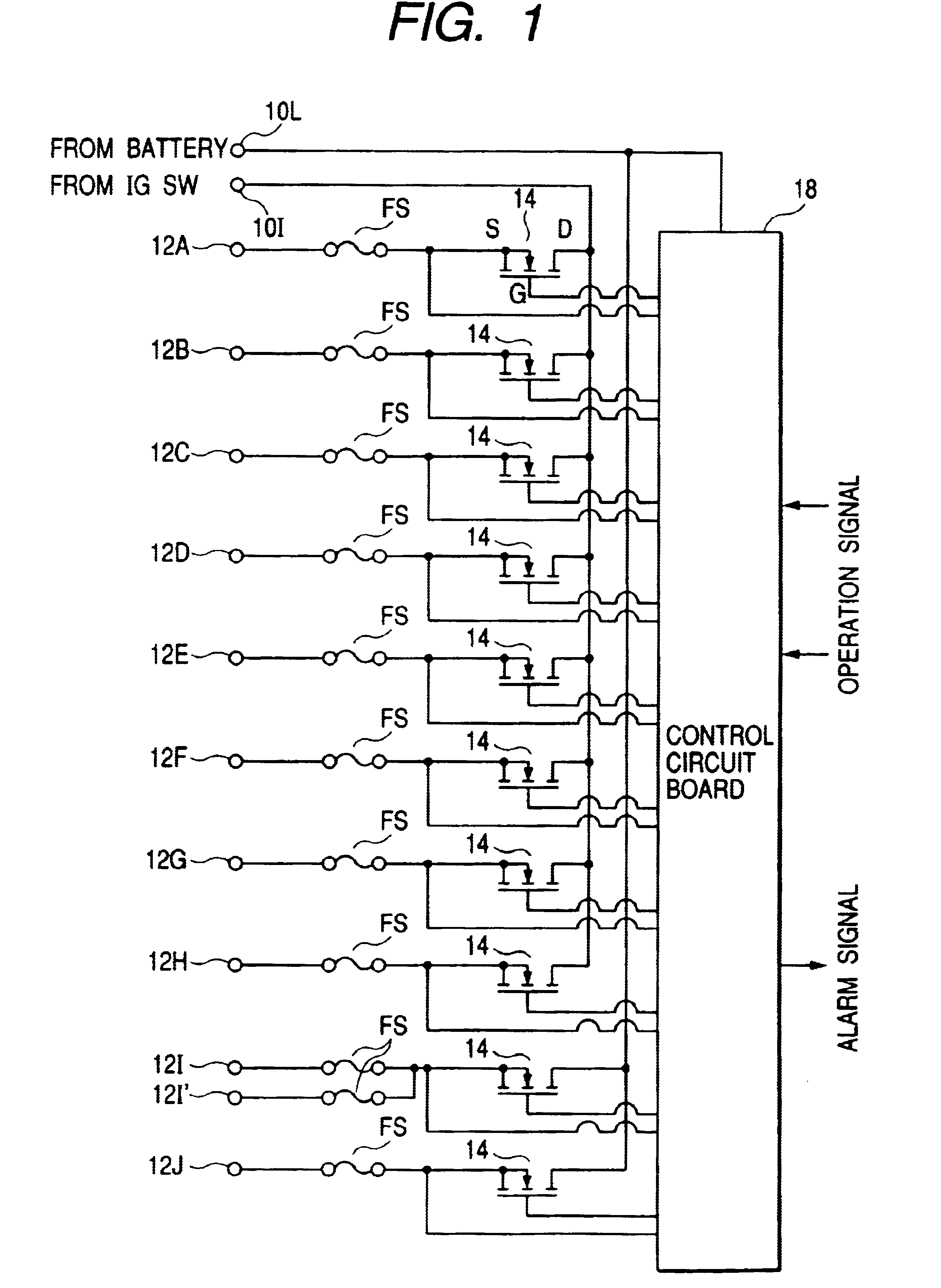
Initially, referring to FIG. 1, a circuit structure of a power distributor according to an embodiment will be described.

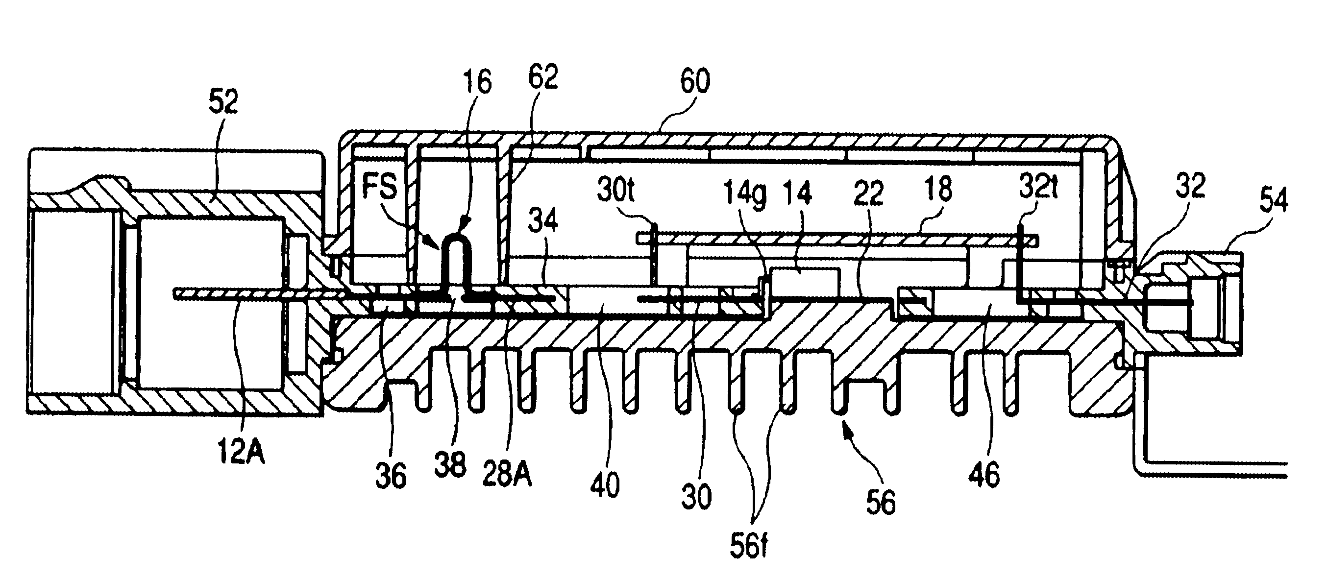
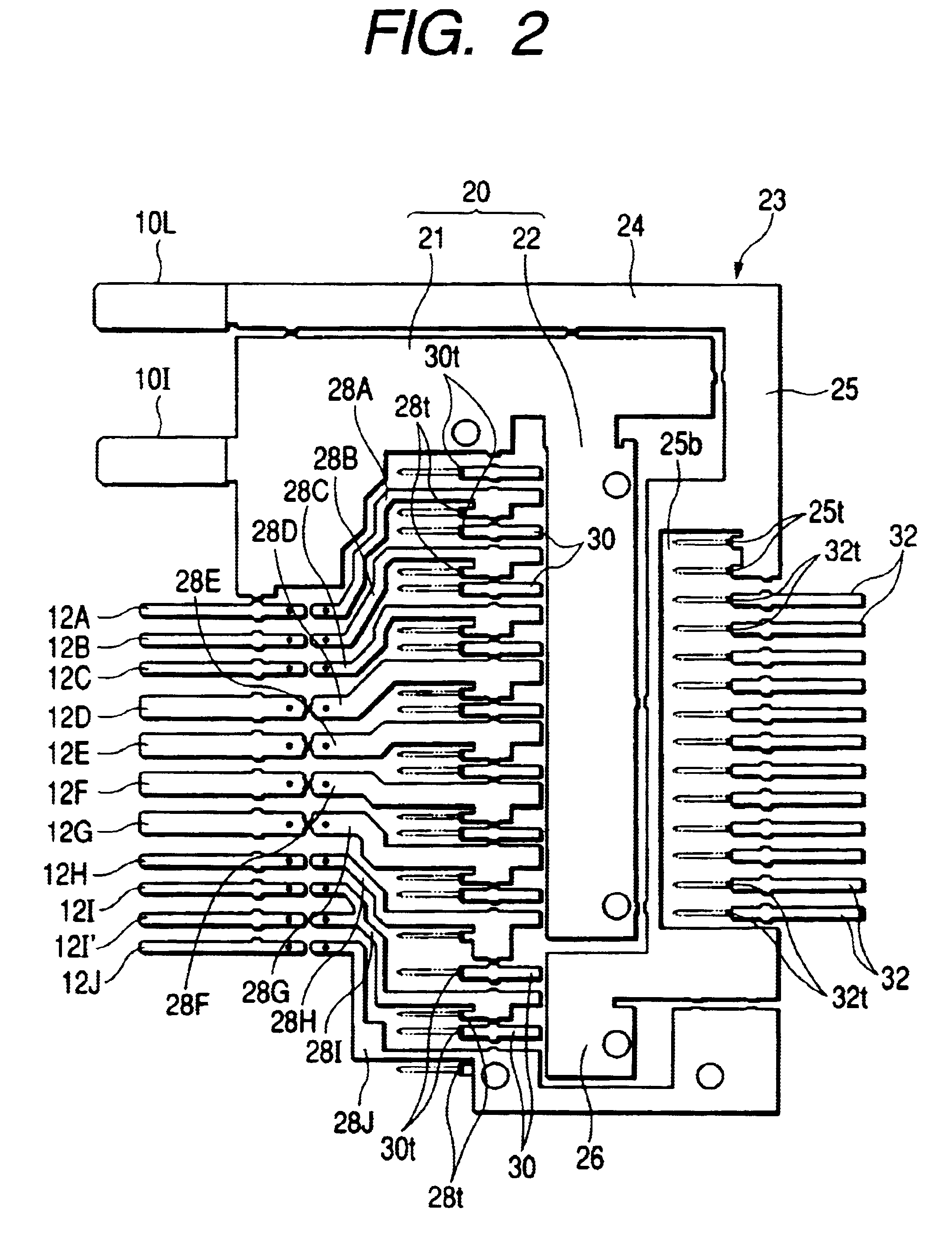
The power distributor comprises a first input terminal 10I and a second input terminal 10L, a plurality of (11 in number in FIG. 1) output terminals 12A, 12B, 12C, 12D, 12E, 12F, 12G, 12I, 12I', 12J, a plurality (10 in number in FIG. 1 of semiconductor switching elements (in the drawing, power MOSFET 14, hereinafter, simply referred to as "FET"), and a control circuit board 18.

The input terminals 10I, and 10L are connected to a common car-power source (for example, a battery), and the first input terminal 10I is connected to the car-power source through an ignition switch, and the second input terminal 10L is connected to the car-power source through a lamp switch.

In the output terminals 12A-12J, the output terminals 12A-12H are respectively connected to electronic units (...


PUM


Abstract

In the power distributor using a semiconductor switching element, input terminals 10I and 10L, output terminals 12A-12J, connected to the element, and more preferably, the board terminals 30 and 32, are structured by a metallic plate, and arranged on the same plane perpendicular to the plate thickness. The metallic plate can be integrated by the resin mold, thereby the structure can be greatly simplified. The metallic plate can be produced by a greatly simple method by which, after the punching out of the metallic plate and the molding of the resin mold, a predetermined portion of the metallic plate is cut and the semiconductor switching element is mounted, and it can contribute to also the reduction of the cost.

Description

1. Field of the InventionThe present invention relates to a power distributor for a vehicle for distributing electric power from a power source such as a battery equipped in the vehicle to a plurality of electronic units such as a unit for a center cluster, a unit for an air conditioner, and a unit for a door, and to a production method thereof.2. Description of the Related ArtConventionally, for distributing electric power from a common car-mounted power source to each electronic unit, an electric connection box is well-known in which a power distributing circuit is structured by laminating plural sheets of bus bar substrates, and fuses and relay switches are assembled therein.Further, recently, in order to realize a size reduction of the electric connection box and the high speed switching control, the power distributor has been developed in which semiconductor switching elements such as FETs are inserted between the input terminal and the output terminal instead of relays. For ex...

Claims


Application Information

Patent Timeline
Patent Type & Authority Patents(United States)
IPC IPC(8): B60R16/02B60R16/023
CPCB60R16/0238
Inventor ONIZUKA, TAKAHIROISSHIKI, ISAOYAMANE, SHIGEKI
Owner AUTONETWORKS TECH LTD
Why Eureka
Try Eureka