Thermo-electric cooler for use in an optical assembly

Inactive Publication Date: 2004-05-04
NORTEL NETWORKS LTD
View PDF5 Cites 15 Cited by
  • Summary
  • Abstract
  • Description
  • Claims
  • Application Information

AI Technical Summary

Benefits of technology

This provides the advantage that each region of the surface has a "neutral region" in which deformation as a result of temperature variation is minimal. By dividing the surface into regions, more of these "neutral regions" are avai

Problems solved by technology

This problem is particularly severe for optical assemblies in which the length of the "optical train" is significant; for example, where there are a plurality of optical components positioned in series along the optical bench.
However, although thermo-electric coolers are operable to maintain optical bench temperature they are themselves still sensitive to

Method used


Image

  • Thermo-electric cooler for use in an optical assembly
  • Thermo-electric cooler for use in an optical assembly
  • Thermo-electric cooler for use in an optical assembly

Examples


Example

Embodiments of the present invention are described below by way of example only. These examples represent the best ways of putting the invention into practice that are currently known to the Applicant although they are not the only ways in which this could be achieved.

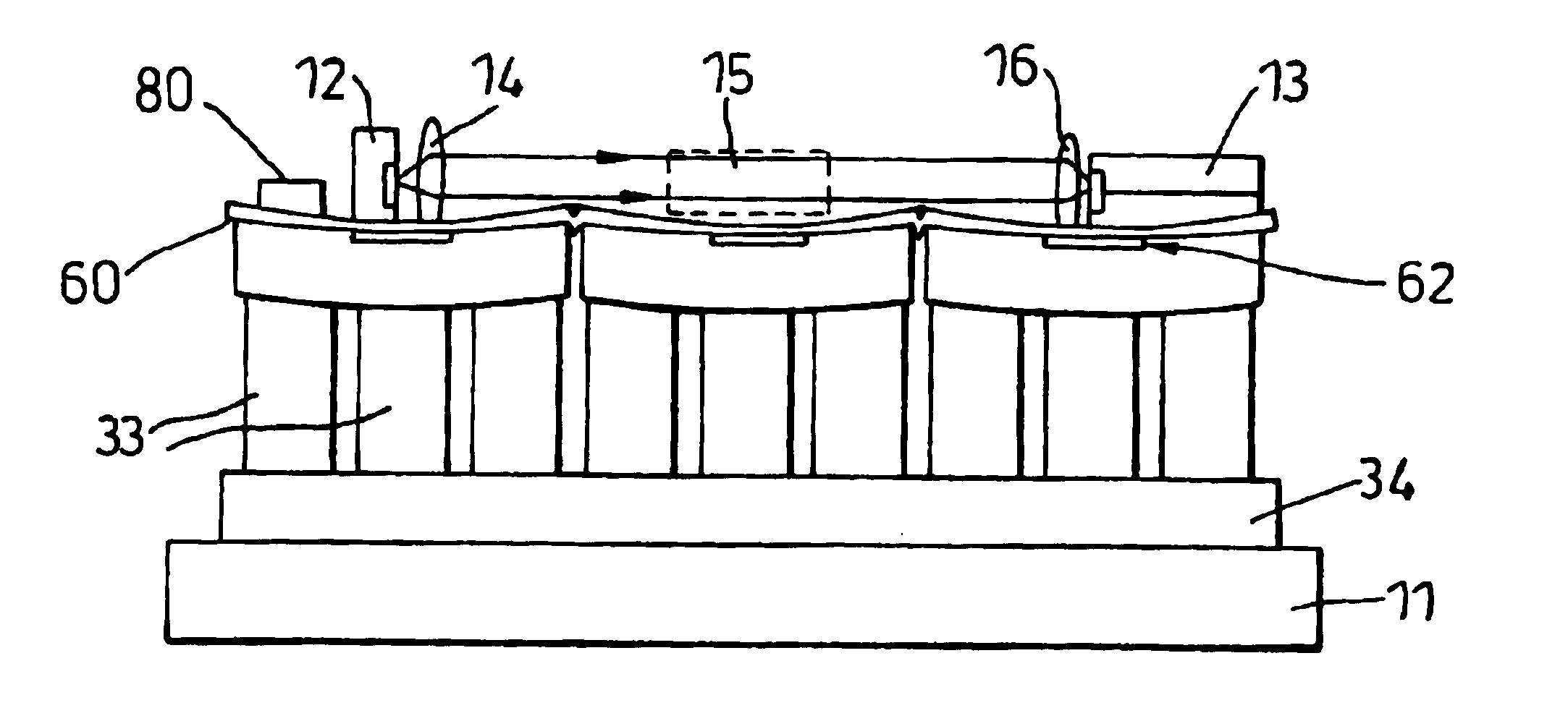
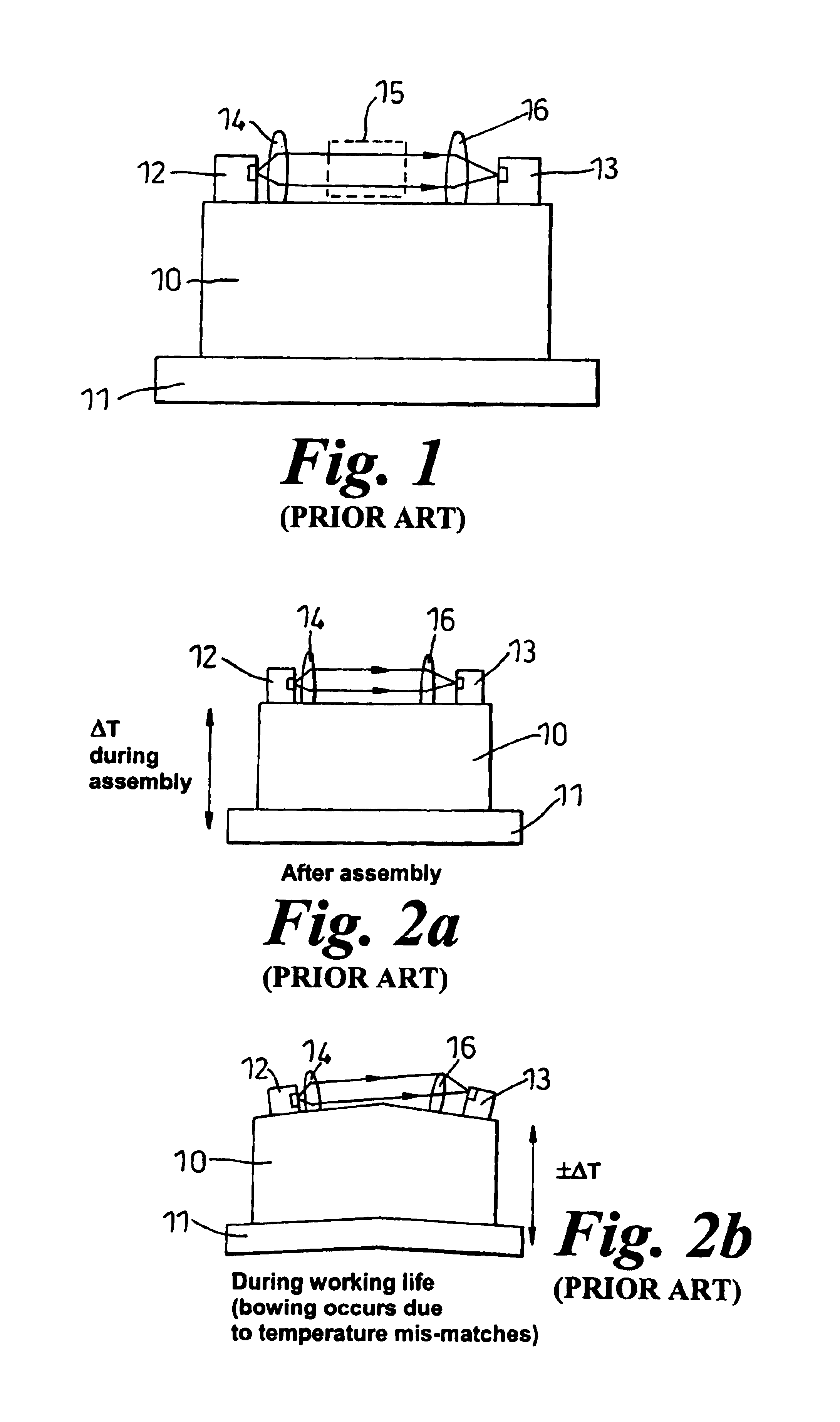
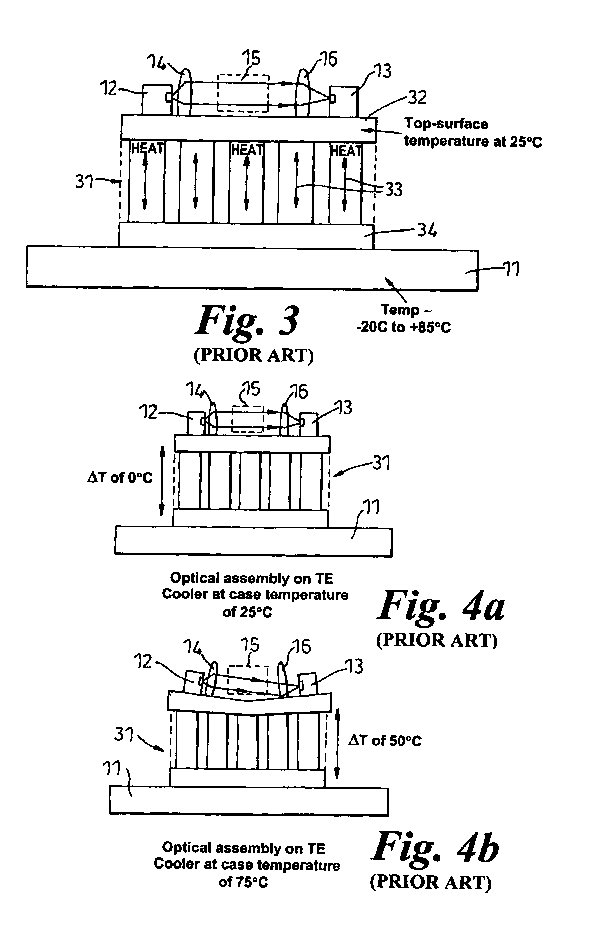
FIG. 1 is a schematic cross-section through a free-space optical train according to the prior art. An optical bench comprising a block of silica 10 rests inside a package or case 11. The optical bench supports a free-space optical train comprising a laser 12, two collimating lenses 14, 16, an optical gadget 15 (which may be any suitable device such as a beam splitter or isolator) and a waveguide 13. These components are arranged in series along an upper surface of the optical bench as illustrated in FIG. 1.

An aim for such free-space optical systems is to ensure maximum light or power coupling efficiency between each component in the optical train. Typically, lenses are used to alter the dimensions of the wavefront to a...


PUM


Abstract

Optical assemblies of the type supported on an optical bench and comprising a one or more components such as lasers, lenses, filters, isolators and waveguides, are sensitive to movement variation. One of the causes of movement is temperature tracking. Previously, thermo-electric coolers have been used to maintain the top-surface temperature of an optical bench within a certain range. However, although thermo-electric coolers are operable to maintain optical bench temperature they are themselves still sensitive to temperature tracking and can deform. Because an optical bench is typically supported on the top surface of a thermo-electric cooler this leads to deformation of the optical bench itself and as a result performance of the optical assembly is affected. An improved design of thermo-electric cooler is described where the top surface of the cooler is divided into separate regions, each having a neutral region in which deformation is minimal. A thermally conductive sheet is placed over each of these regions such that only one temperature monitor is required. Optical components are then supported over the thermally conductive sheet in the neutral regions.

Description

The present invention relates to a thermo-electric cooler for use in an optical assembly.BACKGROUND TO THE INVENTIONOptical assemblies of the type supported on an optical bench and comprising one or more components such as lasers, lenses, filters, isolators and waveguides, are sensitive to movement variation. One of the causes of movement is temperature tracking. The term, "temperature tracking" is used to refer to a temperature dependent variation in the output signal of an optical assembly as a direct result of the movement of components in the optical assembly due to thermal expansion and contraction. This problem is particularly severe for optical assemblies in which the length of the "optical train" is significant; for example, where there are a plurality of optical components positioned in series along the optical bench.An aim of the present invention is therefore to minimise the impact of temperature tracking for optical assemblies.Previously, thermo-electric coolers have bee...

Claims


Application Information

Patent Timeline
IPC IPC(8): H01L35/00H01L35/28H01L35/30F25B21/02H01S3/04H01S3/042H01S5/024H01S5/00
CPCH01L35/00H01L35/30F25B21/02H01S3/042H01S5/02268H01S5/02415H01S5/02446H01S5/02375H10N10/00H10N10/13
Inventor WATTS, JAMESLIU, ANDREWABRAHAM, IAN
Owner NORTEL NETWORKS LTD
Why Eureka
Try Eureka