Blockable bone plate

a bone plate and blockage technology, applied in the field of blockable bone plates, can solve the problems of reducing the surgical effort, so as to reduce the surgical effort, and reduce the cost

Inactive Publication Date: 2004-05-04
MEDARTIS AG
View PDF10 Cites 432 Cited by
  • Summary
  • Abstract
  • Description
  • Claims
  • Application Information

AI Technical Summary

Benefits of technology

Since the complete geometry of the screw holes in the plate can be worked from one side, retooling is not required during machining, thus resulting in overall cost-effective production which can also be executed with precision at a reasonable cost.
In the configuration of the bone plate with a longitudinal axis of the plate in the shape of an arc of a circle (at least in the main segment if the bone plate is provided with a lateral segment attached at one end or both ends), after bending the webs out of the plate plane, as it were over the surface, it is possible to adapt the bone plate closely to the bone. The additional bending in the plate plane is dispensed with, that is to say the setting or twisting over the edge. By means of the circular arc-shaped starting geometry, the bone plate assumes the inclination of a circular section of the jacket surface of a cone. This reduces the surgical effort when adapting the plate and also reduces the losses of strength thereof because of minimal deformation. There is ideal adaptation of the bone plate in its longitudinal extent and the inclination over the plate width.

Problems solved by technology

The relatively small spacer elements that can be fitted complicate the surgical procedure.
Regardless of whether the spacer elements are fixed or can be fitted in place, they do not provide any improved securing of the screws against their inadvertently coming loose.
This system requires the special securing elements and devices and is therefore expensive to manufacture and handle.
The relatively large number of parts means that the operation takes longer and entails more instrumentation and is as a whole made more difficult.
The plate-screw connection according to U.S. Pat. No. 5,709,686 permits satisfactory blocking and an additional securing of the screws, but there are still serious disadvantages, for example:
Even at low torques when the screw is being screwed in, the internal thread in the screw hole can be overscrewed.
Because of the overall geometry of the plate holes, machining has to be done from two directions, which makes the plate production more expensive.

Method used


Image

  • Blockable bone plate
  • Blockable bone plate
  • Blockable bone plate

Examples


first embodiment

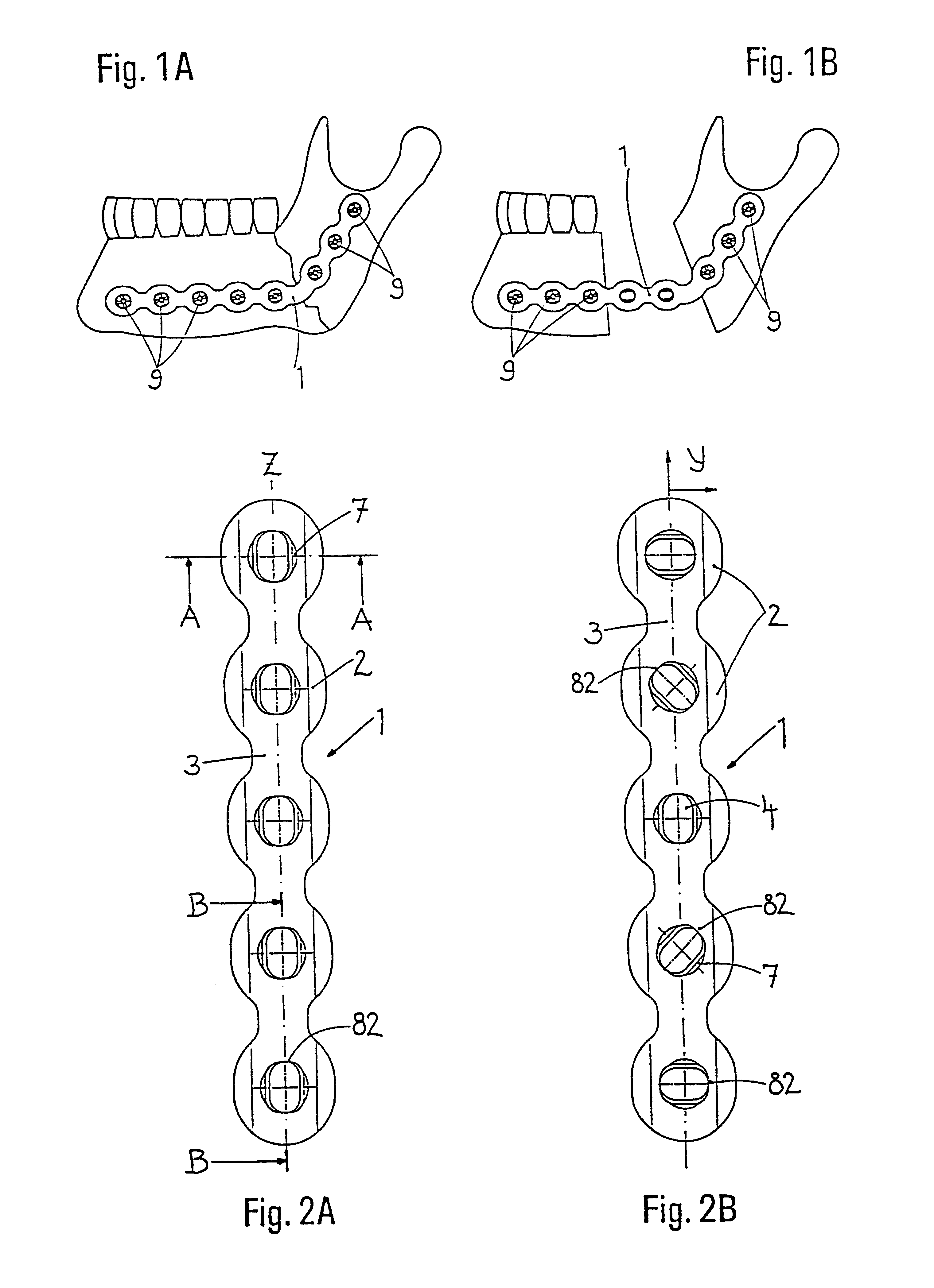
The engagement contour 8 looks like a partial thread, but only at first sight; in fact the engagement contour 8 consists of contour valleys 80 and alternating adjacent contour peaks 81 arranged on the wall of the screw hole 4 and extending parallel to the plate plane Y. The contour valleys 80 and peaks 81 run partially in the peripheral direction in the screw hole 4, i.e. run out to the edges of the engagement contour 8, so that uncontoured wall areas 82 are left there in the screw hole 4. The countersink 7 has a depth which is such that the screw heads are received in a recessed manner. The diameter of the countersink 7 is greater than the clear width of the engagement contour 8. The distance between opposite contour valleys 80 and contour peaks 81 is smaller than the distance between the opposite uncontoured wall areas 82, so that the exit 83 of the screw hole 4 on the lower surface 6 of the plate has an oblong hole shape. The contour valleys 80 and contour peaks 81 forming an eng...

second embodiment

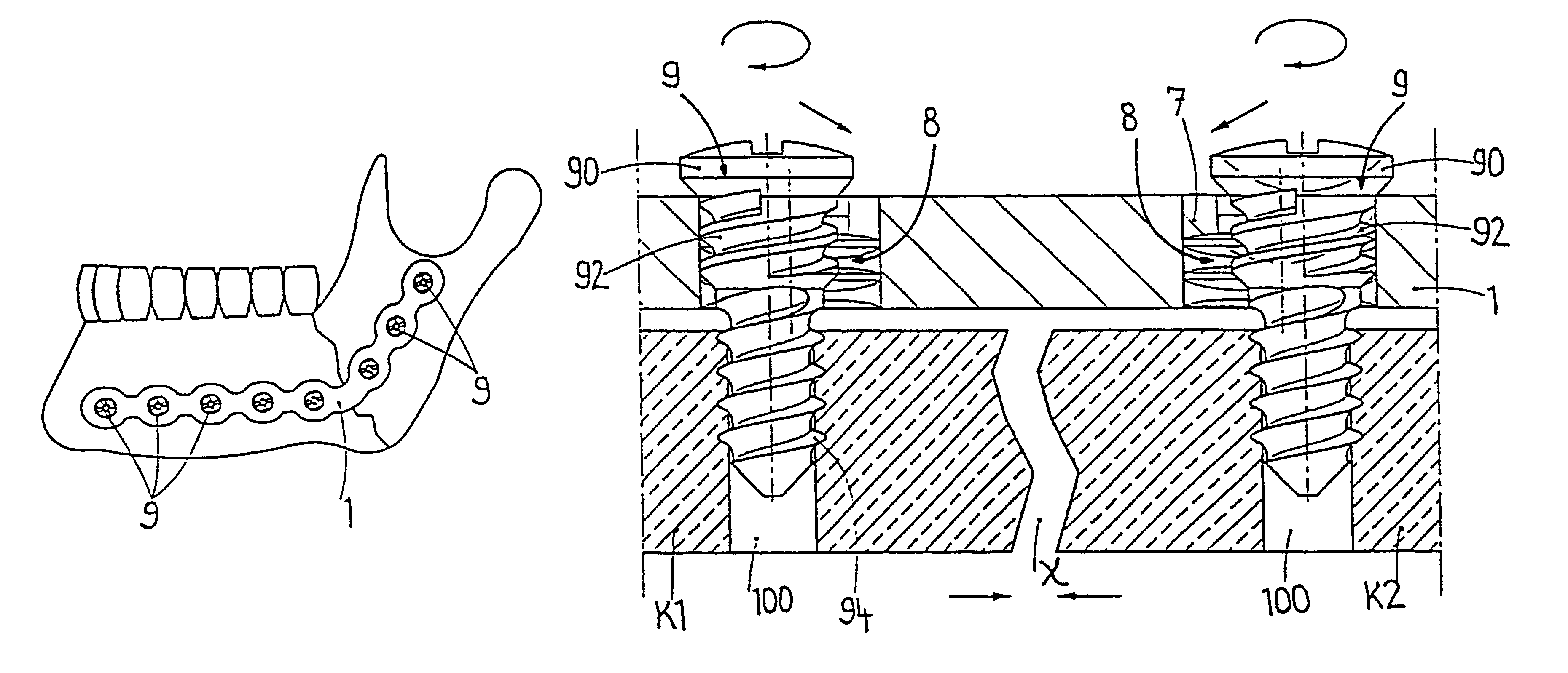
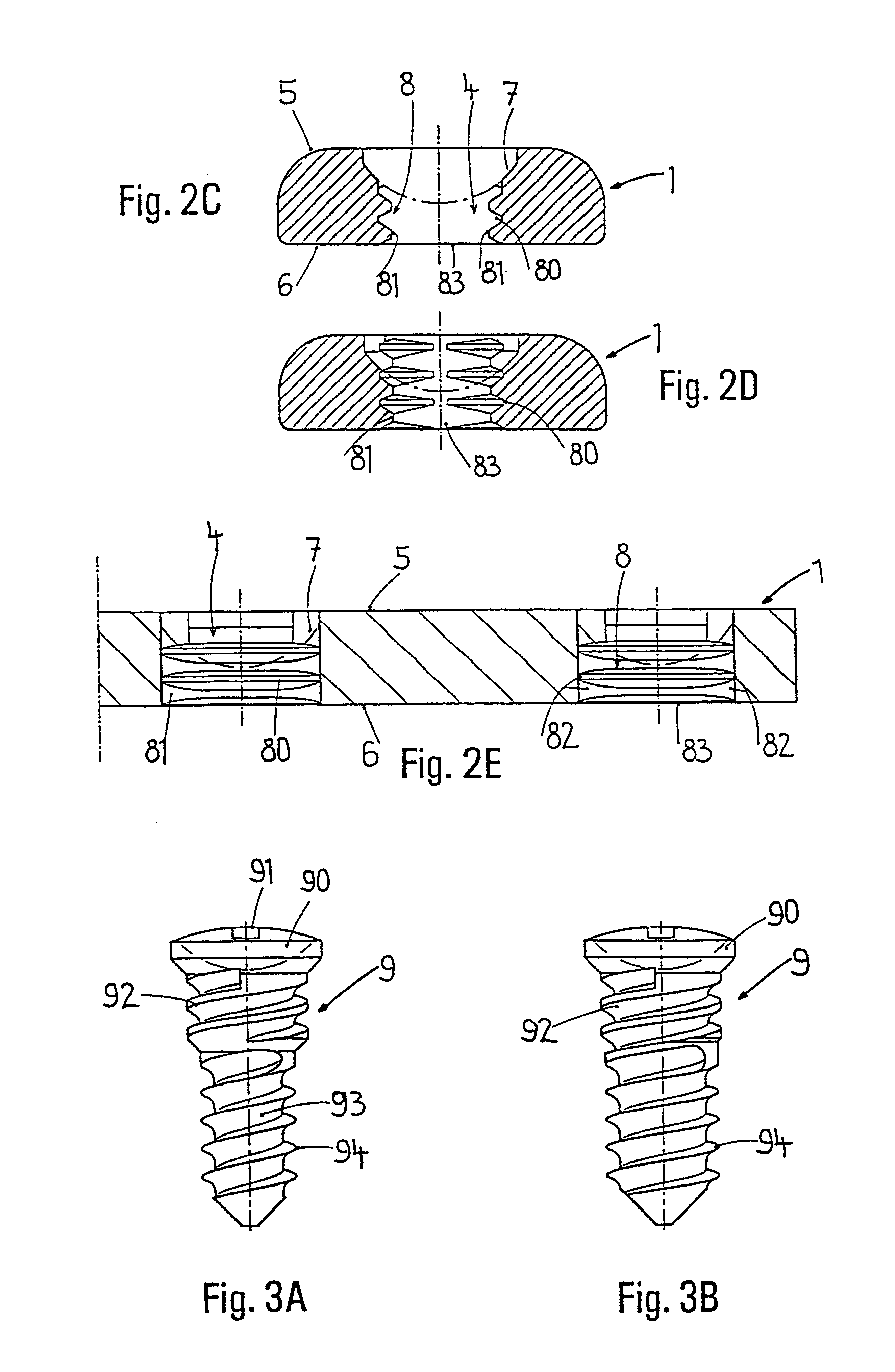
the engagement contour 8 is likewise made up of contour valleys 80 and contour peaks 81 which are worked into the wall of the screw hole 4, parallel to the longitudinal axis Z of the plate, and run out at their ends in uncontoured wall areas 82. The particular feature here lies in the fact that contour valleys 80 and contour peaks 81 lie offset in relation to each other on both sides of the longitudinal axis Z of the plate. In this way the uniform thread on the screw shank 93 acts in the upper part as a blocking thread 92, whose thread teeth engage behind the contour peaks 81, while the lower part acts as a bone thread 94 for insertion into the bone. The screw head 90 with its spherical cap bottom sits in the spherical countersink 7.

FIGS. 7A to 7C

third embodiment

the engagement contour 8 is made up of contour valleys 80 and contour peaks 81 which extend inside the screw hole 4 parallel to the longitudinal axis Z of the plate and are serrated in shape. Here, the contour valleys 80 and contour peaks 81 lie at the same height on both sides of the longitudinal axis Z of the plate and, at the ends of the engagement contour 8, run out in uncontoured wall areas 82. The double-threaded screw 9 also used in this plate-screw connection has a uniform thread along its screw shank 93, the upper part of which engages as a blocking thread 92 under the contour peaks 81, while its lower part is provided as a bone thread 94 for insertion into the bone. The screw head 90 is again recessed in the spherical countersink 7.

FIGS. 8A to 8C


PUM


Abstract

The blockable bone plate consists of a plurality of plate members which are connected to each other via webs. A screw hole is provided in at least some plate members, preferably in each plate member. The screw hole is surrounded by a spherical countersink on the upper surface of the plate. Provided internally in the screw hole there is an engagement contour which consists of contour valleys and contour peaks partially running in a horizontal and radial peripheral direction on the wall of the screw hole. The engagement contour is preferably produced by milling and has for example a pointed, round, trapezoidal or serrated configuration. A blocking thread is provided under the screw head of the screw intended for blocking. As the screw is screwed in, the blocking thread engages in the engagement contour. The particular advantages lie in increased security against the screw coming loose and in the possibility of also inserting the screw through the plate at an inclination. Furthermore, a bone plate is proposed which has the shape of an arc of a circle in the longitudinal axis of the plate and which requires less bending, particularly on the human lower jaw, and adapts to the bone in a more ideal manner.

Description

FIELD OF APPLICATION OF THE INVENTIONThe present invention relates to a blockable bone plate with secured bone screws which serve in particular as a reconstruction system for the maxillofacial region of the human skull, for example for the lower jaw. For the time being, the shorter terms "plate", "screw" and "plate-screw connection" are used. Such plates are used, for example, to strengthen weakened and damaged bone structures. In the case of large continuity defects, the plates have to provide stability over long periods of time and take up the loads which the missing bone would have supported. Plates of this type consist in their simplest form of a straight elongate branch with a multiplicity of plate members, in each of which a screw hole is provided for receiving a screw. The plate can be tailored to the required length, which is done by cutting off surplus plate members, and can be bent to adapt it to the local anatomical situation.The bone plate and a plate-screw connection ha...

Claims


Application Information

Patent Timeline
Patent Type & Authority Patents(United States)
IPC IPC(8): A61B17/68A61B17/80A61B17/58
CPCA61B17/8057A61B17/863A61B17/8071A61B17/8085
Inventor PFEFFERLE, JOACHIMROTH, MICHAELSCHEUBLE, PETERZEUNER, HERMANN
Owner MEDARTIS AG
Why Eureka
Try Eureka