Method and apparatus for cooling hot rolled steel strip, and method for manufacturing hot rolled steel strip

a hot rolled steel and cooling technology, applied in the direction of heat treatment equipment, manufacturing tools, furnaces, etc., can solve the problems of rapid cooling, intermittent cooling, and inability to achieve a cooling speed of 200.degree. c/sec or more for 3 mm sheet thickness

Inactive Publication Date: 2004-05-11
JFE STEEL CORP
View PDF16 Cites 16 Cited by
  • Summary
  • Abstract
  • Description
  • Claims
  • Application Information

AI Technical Summary

Benefits of technology

Use of above cooling apparatus and the cooling method enables to effectively discharge the cooling water from upper surface of the steel strip to manufacture stably the hot rolled steel strip with a fine grain size.
Use of the cooling apparatus and cooling method of the hot rolled steel strip can stably and rapidly cool the steel strip just after the roll mill. In particular, the same cooling condition as the center of the steel strip under tension is available even under non-tension before reaching coiler, resulting in completely equal cooling condition to upper and lower surfaces at the steel strip top.
Restraining occurrence of bend or residual stress after cooling can produce uniform grain size in longitudinal and width directions. This results in uniform product with a high yield rate to supply the hot rolled steel strip with stabilized quality.
This cooling apparatus and cooling method ensures a constant path line of the steel strip using a fluid pressure to prevent defect from occurring without any folding of the steel strip or deforming to an accordion like shape.
This results in an effective discharging the cooling water from upper surface of the steel strip not only to prevent excessive cooling to eliminate bending during cooling and residual stress after cooling but also to manufacture stably the hot rolled steel strip with uniform grain size In longitudinal and width directions.

Problems solved by technology

Therefore, this cooling mode does not ensure an exact symmetrical cooling for the upper and lower surface of the steel strip, resulting in intermittent cooling especially at the upper surface of the steel strip.
This makes a rapid cooling (for example, cooling speed of 200.degree. C. / sec or more for 3 mm in sheet thickness) impossible practically.
Upon rapid cooling of the hot rolled steel strip, the conventional cooling apparatus has been involved in the following problems.
At rapid cooling, a cooling start point is different at the upper and lower surfaces of the steel strip, which causes to generate non-uniformity in material property.
After cooling, cooling water remains at the upper surface of the steel strip to cause excessive cooling at the upper surface.
The excessive cooling is not uniform in a longitudinal direction, resulting in variation in cooling finish temperature in this direction.
In the width direction, cooling water tends to flow from sides of the steel strip to both line sides to cause excessive cooling at the end compared with the center of the strip, fluctuating the temperature finish time.
This makes material property non-uniform.
However, the former method when applying strong cooling is useless because a large amount of cooling water remains on the steel strip.
As a result, the restriction roll if provided at the roller table disturbs safe passing of the strip, which is difficult to apply the roll as the cooling apparatus for the runout.
Strong cooling if applied at the top of the vibrating steel strip at non-restricted state will further escalate vibration of the top end of the steel strip unavoidably to damage due to contact with the restriction roll.
Change in the cooling water ratio, however, will unbalance the cooling effect to upper and lower surfaces especially to make unavoidably material property non-uniform.
In addition, the strong cooling necessary for changing in material property is difficult because of insufficient cooling at the lower surface.
This machine, however, is difficult to hold uniform interval between the cooling water guide and the steel strip surface because the steel strip top is transferred waving up and down.
This method if applied for a thinner steel strip causes sticking trouble because of disturbing smooth passage at touching the steel strip top to the transfer roll.
Such steel strip failed in its shape cannot be pressed by the guide roll, resulting in another leveler provided for flat shape to escalate working man-hour.
But this apparatus is not available for installing a detecting sensor for steel strip temperature and sheet thickness during rolling step as significant items in quality control of the steel strip.
However, cooling is difficult to start at the steel strip top end, because it vibrates up and down at free state.
If not, the steel strip top end might be crashed into the roll clearance or be broken at the half way the steel strip top end once crashed into the upper or lower rolls generates up and down vibration due to reaction force to disturb stable passage, especially for thinner strip.
Rolls if arranged densely at both upper and lower sides will disturb strong cooling because the cooling nozzle area is narrowed.

Method used


Image

  • Method and apparatus for cooling hot rolled steel strip, and method for manufacturing hot rolled steel strip
  • Method and apparatus for cooling hot rolled steel strip, and method for manufacturing hot rolled steel strip
  • Method and apparatus for cooling hot rolled steel strip, and method for manufacturing hot rolled steel strip

Examples


first embodiment

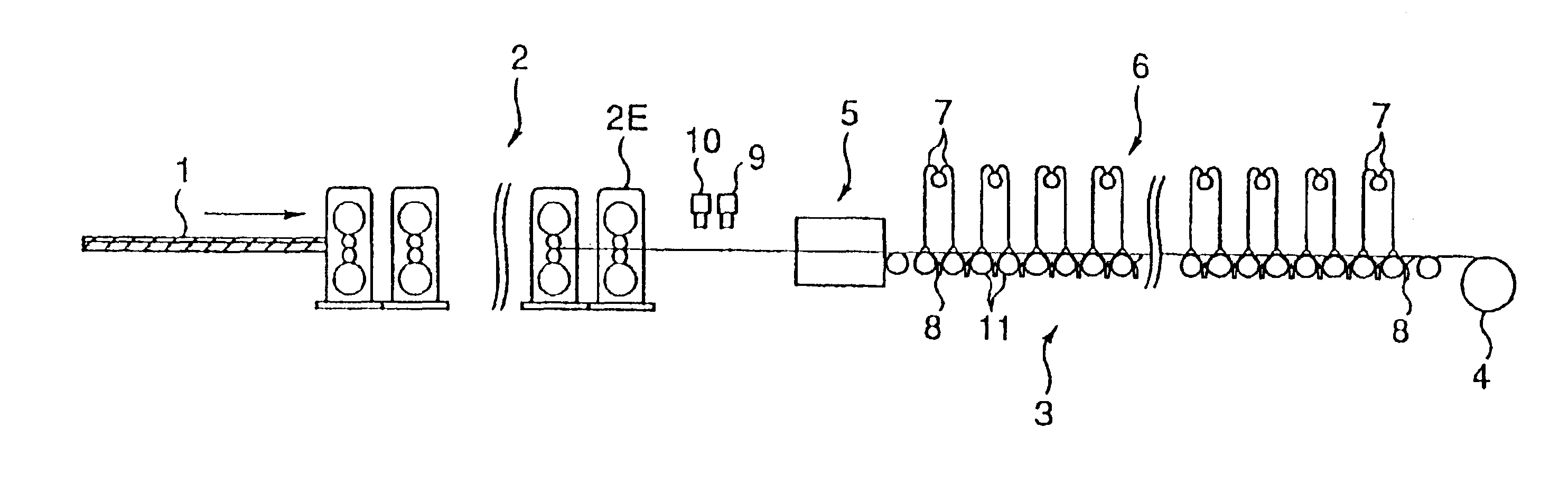
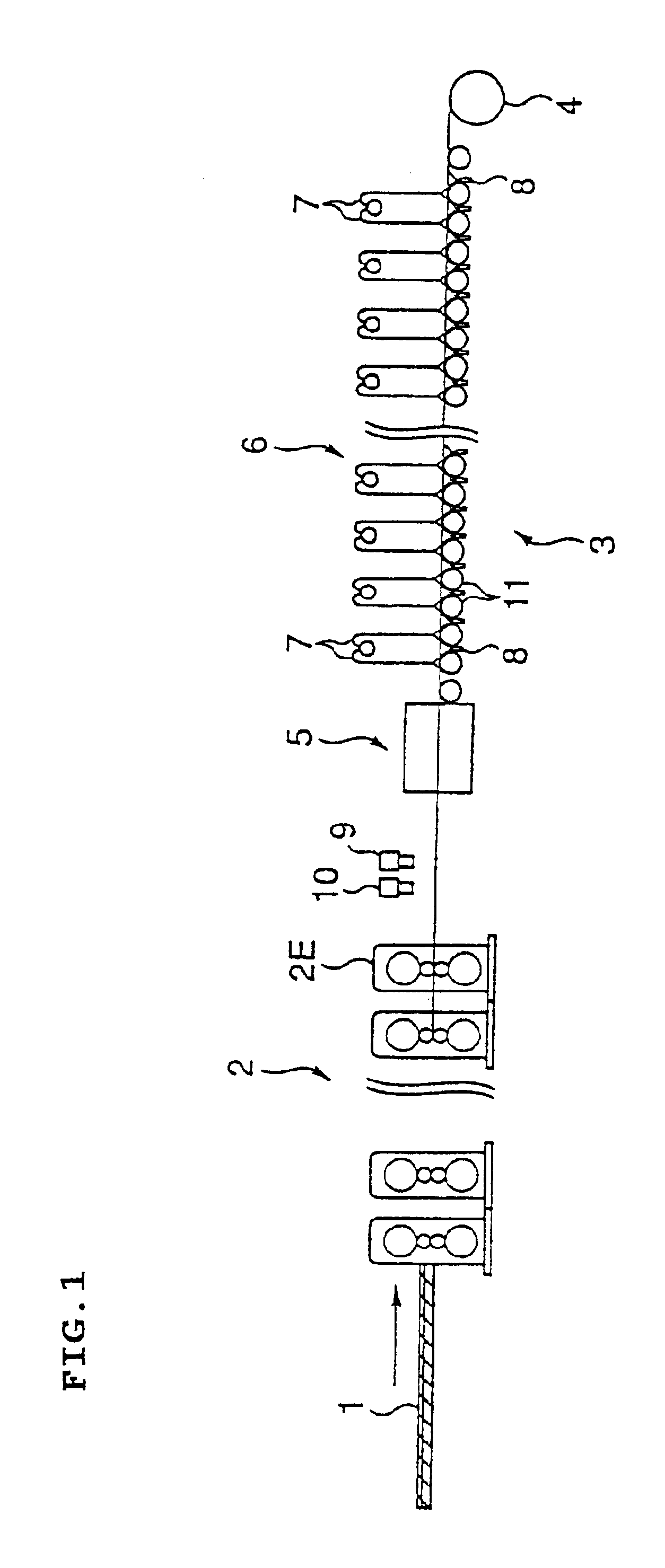
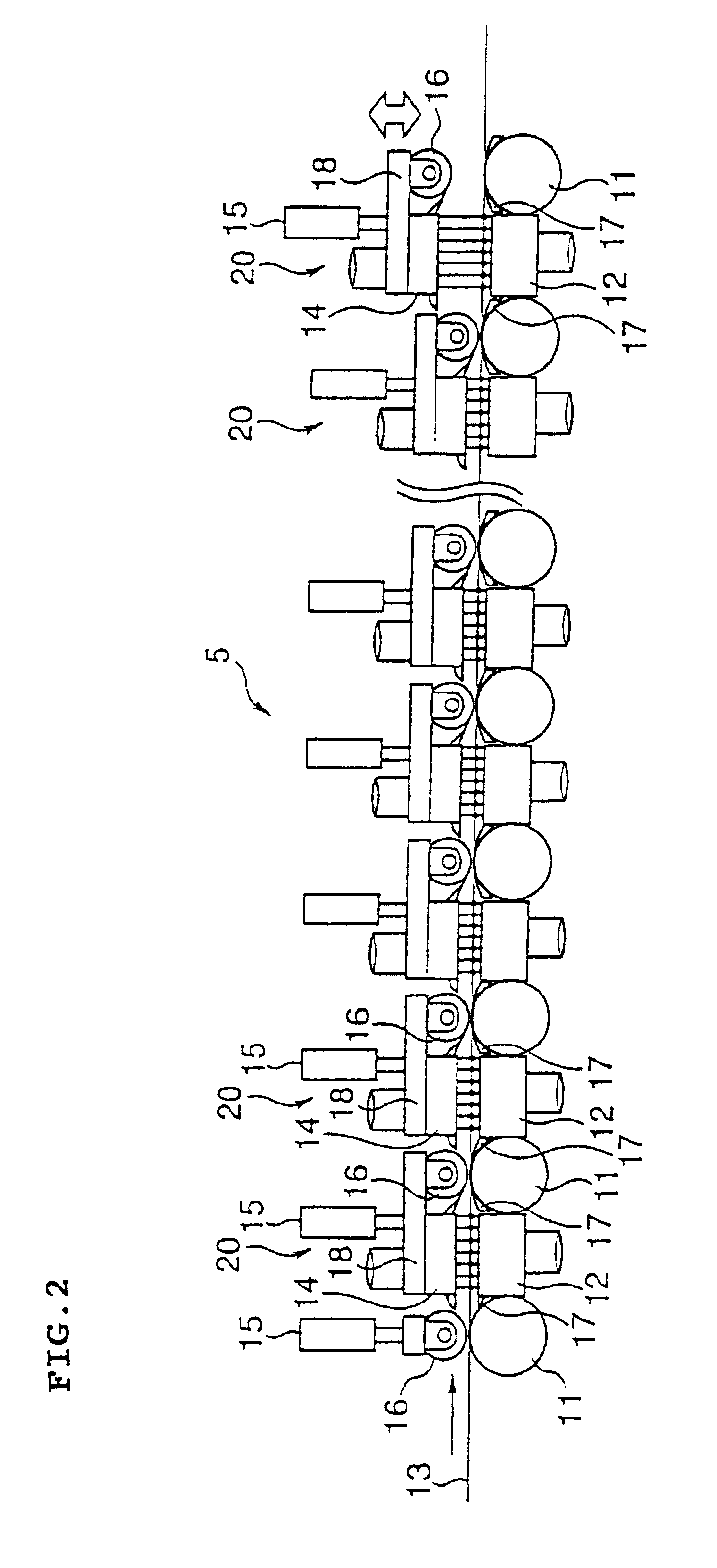
FIG. 1 shows schematically a manufacturing equipment of a hot rolled steel strip of the first embodiment and FIG. 2 indicates schematically a first cooling apparatus.

A rough bar 1 rolled by a roughing mill is transferred on transfer rolls of a transfer means and is guided to a runout table 3 behind a final finishing mill 2E after rolling sequentially to the specified thickness by seven stands of continuous finishing mill 2. Most areas of the runout table 3 are equipped with a cooling apparatus (cooling means) where a steel strip is cooled and rolled up by a coiler to form a hot rolled coil.

The narrower a mutual distance between transfer rolls 11 comprising the runout table the more stable a plate passage ability is, but if too narrowed no space is available to arrange the cooling apparatus to extend a cooling length to deteriorate a cooling efficiency. Therefore, the mutual distance between the transfer rolls 11 is desirable to be from a roll diameter plus 100 mm to about three time...

second embodiment

FIG. 3 shows a schematic drawing of a manufacturing equipment of a hot rolled steel strip at the

A rough bar 1 rolled at a roughing mill is transferred on the transfer rolls to roll to the specified thickness by passing seven units of continuous finishing mill 2 and finally is guided to a runout table 3 behind the final finishing mill 2E. The runout table is 80 m in an entire length typically comprising a cooling apparatus at which the plate is cooled and rolled up by a coiler 4 to form the hot rolled coil.

A cooling apparatus (cooling means) 25 provided at the runout table 3 comprises plural circular laminar nozzles 26 arranged at the specified pitch at the upper surface of the runout table 3 and plural spray nozzles 27 provided between the transfer rolls 11 comprising the transfer means of the steel strip at the lower side. A water breaking device (water breaking means) described later is arranged at the outlet of the cooling apparatus 25.

A water breaking device 28 above and its per...

third embodiment

FIG. 5 shows a schematic drawing of a manufacturing equipment of a hot rolled steel strip at the A rough bar 1 rolled at a roughing mill is transferred on transfer rolls to roll to the specified thickness by passing seven units of continuous finishing mill 2 and finally is guided to a runout table 3 installed extending to 80 m behind a final finishing mill 2E. Most of the runout table comprises a cooling apparatus cools at which the steel strip 13 is cooled and rewound by the coiler 4 to form the hot rolled coil.

The runout table 3 is equipped with a proximity cooling apparatus 34 described later of about 15 m in length and after with a water breaking device 28A described later is provided.

The cooling apparatus 34 above comprises as shown in FIG. 6. The drawing shows the rotating transfer rolls 11 of 350 mm in diameter are arranged at about 800 mm pitch in the longitudinal direction at the lower side. Between the transfer rolls 11, the lower cooling nozzles 35 are provided for about...


PUM

PropertyMeasurementUnit
distanceaaaaaaaaaa
thicknessaaaaaaaaaa
thicknessaaaaaaaaaa

Abstract

A lower surface cooling box 12 is arranged between transfer rolls 11 on a runout table 3 and an upper cooling box 14 moving freely is arranged at a position corresponding to the cooling box 12 to eject cooling water to the steel strip symmetrically in the vertical direction. The steel strip passes the center of converge of cooling water from upper and lower surfaces of the steel strip. A water breaking roll 16 is provided elevating freely at least at the outlet side rotating at the same peripheral speed as the transfer rolls and is rotated to lower concurrently with passing of the steel strip top at the cooling apparatus. The upper cooling box is also lowered concurrently to cool the steel strip.

Description

The present invention relates to an apparatus and a method for cooling a hot rolled steel strip having a high temperature and a method for manufacturing the hot rolled steel strip.DESCRIPTION OF THE RELATED ARTSIn general, a hot rolled steel strip is manufactured in a step where a slab is heated to the specified temperature in a heating furnace and is rolled to the required thickness by a rough rolling mill to form a rough bar, and finally the resultant bar is rolled by a continuous hot rolling mill having plural rolling stands. The hot rolled steel strip is cooled at a cooling stand on a runout table and then is coiled by a coiler.An online cooling apparatus to transfer as rolled high temperature steel strip and to continuously cool before coiling by the coiler should be first designed to consider steel strip transferring ability.For example, for cooling an upper surface of the steel strip, circular laminar cooling nozzles can be provided at an upper area of the steel strip transfe...

Claims


Application Information

Patent Timeline
Patent Type & Authority Patents(United States)
IPC IPC(8): B21B45/02B21B37/00B21B37/68B21B39/00C21D9/573
CPCB21B45/0218C21D1/667C21D8/00C21D8/04B21B37/007B21B37/68B21B39/006B21B45/0281C21D9/573
Inventor FUJIBAYASHI, AKIOIMADA, SADANORIHINO, YOSHIMICHIMINOTE, TORUMOTOYASHIKI, YOICHIIKEMUNE, SHOZO
Owner JFE STEEL CORP
Why Eureka
Try Eureka