Liquid crystal display device

a liquid crystal display and display device technology, applied in non-linear optics, instruments, optics, etc., can solve problems such as rubbing irregularities, dislocation and light leakage,

Inactive Publication Date: 2004-05-11
SEMICON ENERGY LAB CO LTD
View PDF10 Cites 30 Cited by
  • Summary
  • Abstract
  • Description
  • Claims
  • Application Information

AI Technical Summary

Problems solved by technology

In particular, the occupied ratio of pixels in which disclinations and light leakage developing due to horizontal direction electric fields is large enough that it cannot be ignored in liquid crystal display devices in which the pixels are formed at a very fine pitch, such as that of a projecting liquid crystal display device.
Disclination and light leakage due to horizontal direction electric fields become problems in particular when the pixel area is small, and the proportion of the pixel occupied by the disclination and the light leakage is large enough that it cannot be ignored.
There is a concern that rubbing irregularities may occur if the fiber tips of a rubbing cloth are disordered, and therefore the determination of an upper limit for the height of the convex portion is necessary in order to manufacture a liquid crystal panel.

Method used


Image

  • Liquid crystal display device
  • Liquid crystal display device
  • Liquid crystal display device

Examples


embodiments

[Embodiment 1]

An embodiment of the present invention is explained using FIGS. 21A to 25.

Note that a description is set forth regarding a step for fabricating a pixel TFT; a switching element of the pixel portion and TFTs for driver circuit (a signal line driver circuit and a scanning line driver circuit) provided in the pixel portion of a display device using the driver method of the present invention and periphery portion of the pixel portion. For the simplicity of the explanation, a CMOS circuit, which is a fundamental structure circuit for the driver circuit portion, and the n-channel TFT for the pixel TFT of the pixel portion are shown in figures by a cross-sectional figure according to the path.

First, as shown in FIG. 21A, a base film 401 made of an insulating film such as a silicon oxide film, a silicon nitride film, or a silicon oxynitride film, is formed on a substrate 400 made of a glass such as barium borosilicate glass or aluminum borosilicate glass, typically a glass suc...

embodiment 2

[Embodiment 2]

A portion of the method of manufacturing the active matrix substrate manufactured by Embodiment 1 can be applied to a reflection type liquid crystal display device.

Processing is first performed in accordance with FIGS. 21A to 22C of Embodiment 1.

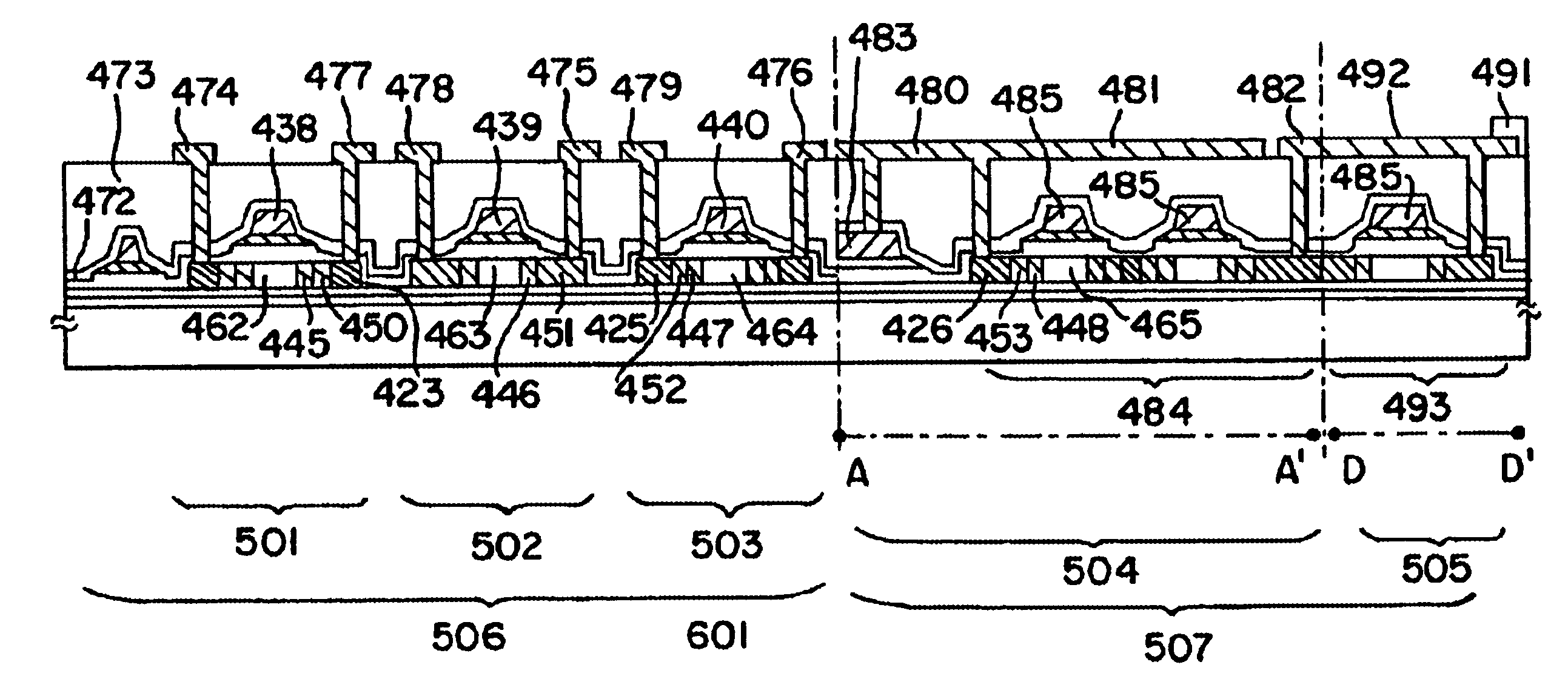
The first interlayer insulating film 472 is then formed from a silicon oxynitride film having a thickness of 100 to 200 nm, as shown in FIG. 27. An acrylic resin film or a polyimide film is then formed with a thickness of 1.8 .mu.m on the first interlayer insulating film 472 as the second interlayer insulating film 473. An etching process is performed next in order to form contact holes.

Next, as shown in FIG. 28, a photolithography process is performed using a photosensitive resin film, and the convex portion 600 is formed having a thickness of 0.32 .mu.m on the source wiring 483. A material in which JSR Corporation product BPR-107VL is diluted by PGMEA (propylene glycol monomethyl ether acetate), reducing its viscosity, is use...

embodiment 3

[Embodiment 3]

In this embodiment, the manufacturing process of an active matrix liquid crystal display device from the active matrix substrate manufactured in Embodiment 1 is described below. FIG. 26 is used for explanation.

First, in accordance with Embodiment 1, the active matrix substrate is obtained. FIG. 26 shows a cross-sectional view taken along the line A-A' and C-C' of the pixel portion of the active matrix substrate shown in FIG. 25. In an active matrix substrate, the driver circuit portion 506 and the pixel portion 507 are formed.

First, an orientation film 512 is formed on the active matrix substrate, and is subjected to a rubbing process. Note that, in this embodiment, before the formation of the orientation film 512, a columnar spacer for maintaining a gap between the substrates is formed at a desired position by patterning an organic resin film such as an acrylic resin film. The columnar spacer having 4.0 .mu.m height is used in this embodiment. Further, spherical space...


PUM

PropertyMeasurementUnit
distanceaaaaaaaaaa
distanceaaaaaaaaaa
widthaaaaaaaaaa

Abstract

Disclination of an active matrix liquid crystal display device is reduced. Portions of pixel electrodes are formed so as to mutually overlap with a convex portion. If the height of the convex portion is too tall, the amount of light leakage increases due to liquid crystals orienting diagonally with respect to a substrate surface. (See FIG. 1C.) If the height of the convex portion is low, the disclination reduction effect is low. The optimal convex portion height is thus determined.

Description

1. Field of the InventionThe present invention relates to a semiconductor device having circuits structured by electric field effect transistors (FETs), for example, thin film transistors (TFTs), and to a method of manufacturing the semiconductor device. The present invention relates, for example, to a semiconductor device, typically a liquid crystal display panel, and to an electronic device in which such a semiconductor device is mounted as its component.Note that, throughout this specification, the term electro-optical device indicates general devices for performing shading display by changing an electrical signal, and that liquid crystal display devices and display devices using electroluminescence (EL) are included in the category of electro-optical device.Note also that, throughout this specification, the term element substrate indicates general substrates on which active elements such as TFTs and MIMs are formed.2. Description of the Related ArtTechniques of structuring thin ...

Claims


Application Information

Patent Timeline
Patent Type & Authority Patents(United States)
IPC IPC(8): G02F1/1333G02F1/13G02F1/1343
CPCG02F1/1333G02F1/133707G02F1/136209G02F1/134336G02F2001/13373G02F2001/133776G02F1/13373G02F1/133776
Inventor HIRAKATA, YOSHIHARUHAMAMOTO, YURIKOSATAKE, RUMO
Owner SEMICON ENERGY LAB CO LTD
Why Eureka
Try Eureka