Spacecraft and aerospace plane having scissors wings

a technology of scissors and aerospace planes, applied in the field of spacecraft and aerospace planes, can solve the problems of increasing the structural weight of the wings, limiting the flexibility of forming different launch configurations, and increasing the weight of the boosters

Inactive Publication Date: 2004-06-08
CHEN ZHUO
View PDF27 Cites 59 Cited by
  • Summary
  • Abstract
  • Description
  • Claims
  • Application Information

AI Technical Summary

Benefits of technology

First, if spacecraft are launched vertically like the Space Shuttle, the invention can make them flexibly form different launch configurations by connecting with other vehicles. When a spacecraft is at vertical launch position, both of the main wings are yawed or turned so that their long axes are generally parallel with the longitudinal axis of the spacecraft's fuselage. By this way, the spacecraft does not have main wings that stick out to prevent it from connecting with other vehicles.
Second, if spacecraft and aerospace planes take-off like aircraft or gliders, the invention can make them achieve good horizontal take-off performance. During horizontal take-off, both of the main wings are yawed to be either generally perpendicular to the longitudinal axis of the fuselage of a spacecraft or aerospace plane or only have small sweep angles. By this way, the main wings can have high aspect ratio to achieve high lift-to-drag ratio (L / D) at low speed, making the spacecraft or aerospace plane able to become airborne at relatively low speed with low engine thrust or towing force.
Third, if spacecraft and aerospace planes are carried or towed to be airborne and launched in the mid-air, the invention can help them smoothly separate from the aircraft carrying or towing them and quickly achieve steady and sustainable flying condition after the separation. No matter the separation occurs at subsonic or supersonic speed, a spacecraft or aerospace plane can adjust the yaw angle of its main wings to have an optimized aerodynamic character for the separation and then quickly adjust the yaw angle to fly on its own.
Forth, the invention can make spacecraft and aerospace planes achieve efficient climb and acceleration in the air at subsonic, transonic, and supersonic speed after their horizontal take-off or horizontal launch. A spacecraft or aerospace plane with scissors wings only needs relatively low engine thrust and low fuel consumption during its climb and acceleration in the air because it can maximize its lift-to-drag ratio (L / D) at a wide range of speed by adjusting the yaw angle of its main wings. This efficiency can save fuel for longer range, higher orbital height, or more payload.
Fifth, during the return flights of spacecraft and aerospace planes after they finish their space or hypersonic flights, the invention can make them achieve efficient and effective controlled flight in the air at supersonic, transonic, and subsonic speed. Also due to scissors wings' ability to maximize lift-to-drag ratio (L / D) at a wide range of speed, a spacecraft or aerospace plane with scissors wings can have better gliding performance, needs smaller engine(s), and consumes less fuel during its return flight than the ones with other aerodynamic configurations like low aspect ratio wings.
Sixth, the invention can make spacecraft and aerospace planes achieve good landing performance. During landing, both of the main wings are yawed to be generally perpendicular to the longitudinal axis of the fuselage of a spacecraft or aerospace plane or only have small yaw angle. By this way, the spacecraft or aerospace can have a high aspect ratio configuration to achieve low approach speed. The low approach speed makes it land on short runways, have lightweight landing gears because the impact load for touchdown is also low, and have lighter breaks on landing gears.

Problems solved by technology

These fixed wings stick out from the fuselages of fly back boosters thus limit the flexibility of forming different launch configurations by connecting a fly back booster with other fly back booster(s) and / or other vehicle(s).
A fly back booster with wings of low aspect ratio requires relatively high engine thrust to fly at low speed, has high landing speed, and needs long runway for landing because this kind of wings have low lift-to-drag ratio (L / D) at low speed.
This design increases the booster's weight not only by adding a folding / unfolding system but also by increasing the wings' structural weight because the structures of foldable wings are not continuous thus are heavier than wings that are not foldable.
However, oblique wing has inherent aerodynamic disadvantages that may prevent it from being used on fly back boosters.
That is, when the oblique wing is yawed at an angle so that half of the oblique wing becomes a swept-forward wing and another half becomes a swept-back wing, the roll control and pitch control of the fly back booster is coupled, making it difficult to control and maintain stability.
This inherent problem makes oblique wing difficult to be used on fly back boosters.
These wings do not give the Space Shuttle good performance at low speed and landing.
The sticking out fixed sweep angle fixed wings of the reusable launch vehicle limit the ways to connect boosters onto the reusable launch vehicle and force the boosters to have foldable wings that are heavy and complex.
Shown in the patent, the reusable launch vehicle also has a pair of fixed sweep angle, low aspect ratio wings, The low lift-to-drag ratio (L / D) feature of these wings at low speed makes the reusable launch vehicle needs relatively high engine thrust and high fuel consumption to take-off and climb to high altitude in the air.
However, both the large delta wings with big wing area and variable sweep wings are heavy, making the reusable launch vehicle less efficient.
The variable X-wing is easy to cause unstable conditions when it is being rotated to switch between the high speed wings and low speed wings, making it difficult to be used on reusable launch vehicles.
This kind of low aspect ratio configurations has low lift-to-drag ratio (L / D) at low speed, making the aerospace plane need long runway to take-off and land, has high fuel consumption while flying at low speed, and reguire high engine thrust thus bigger engine(s) to take-off, climb and accelerate to its cruising altitude, and land.

Method used


Image

  • Spacecraft and aerospace plane having scissors wings
  • Spacecraft and aerospace plane having scissors wings
  • Spacecraft and aerospace plane having scissors wings

Examples


Embodiment Construction

Fly Back Booster

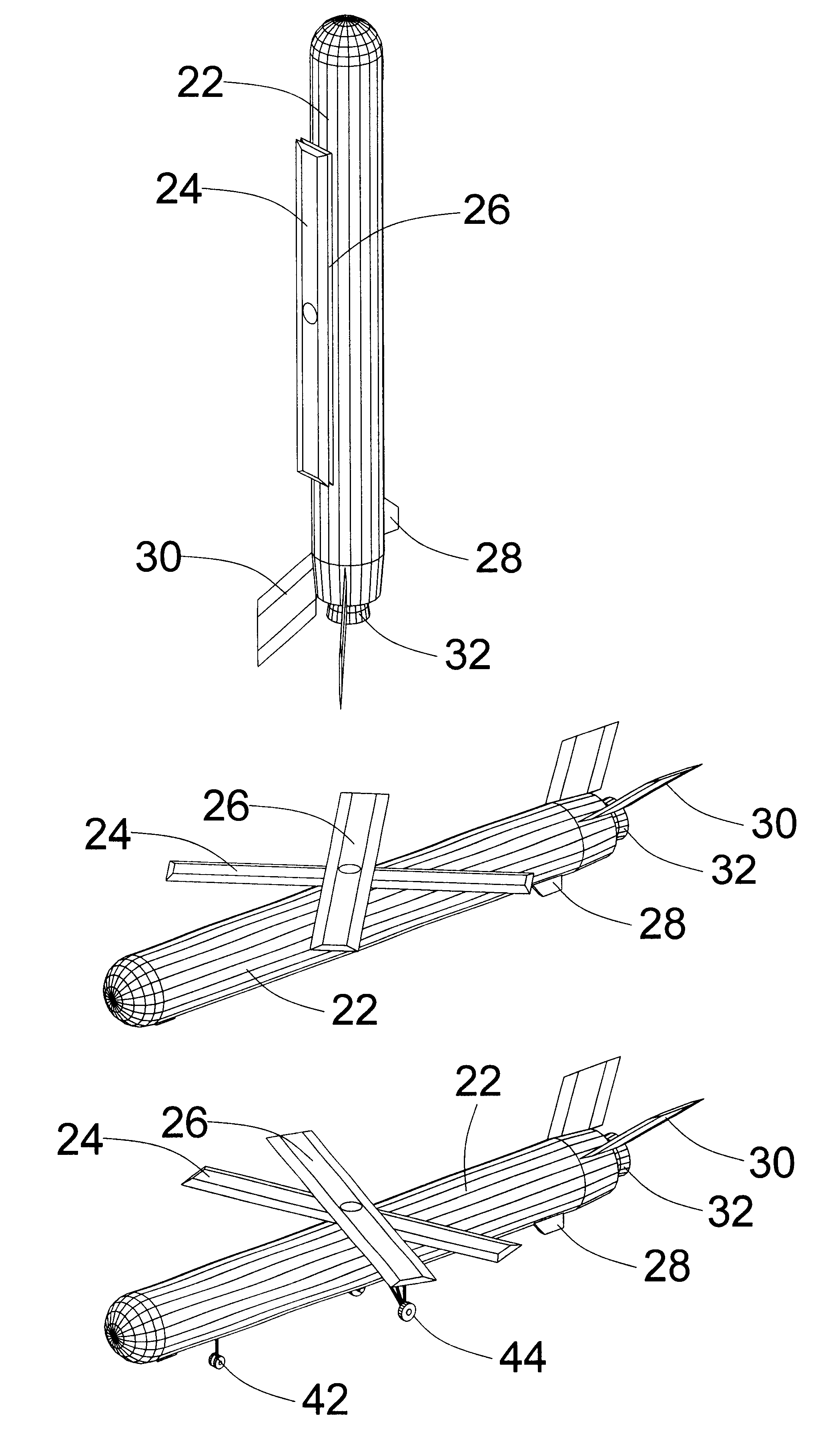
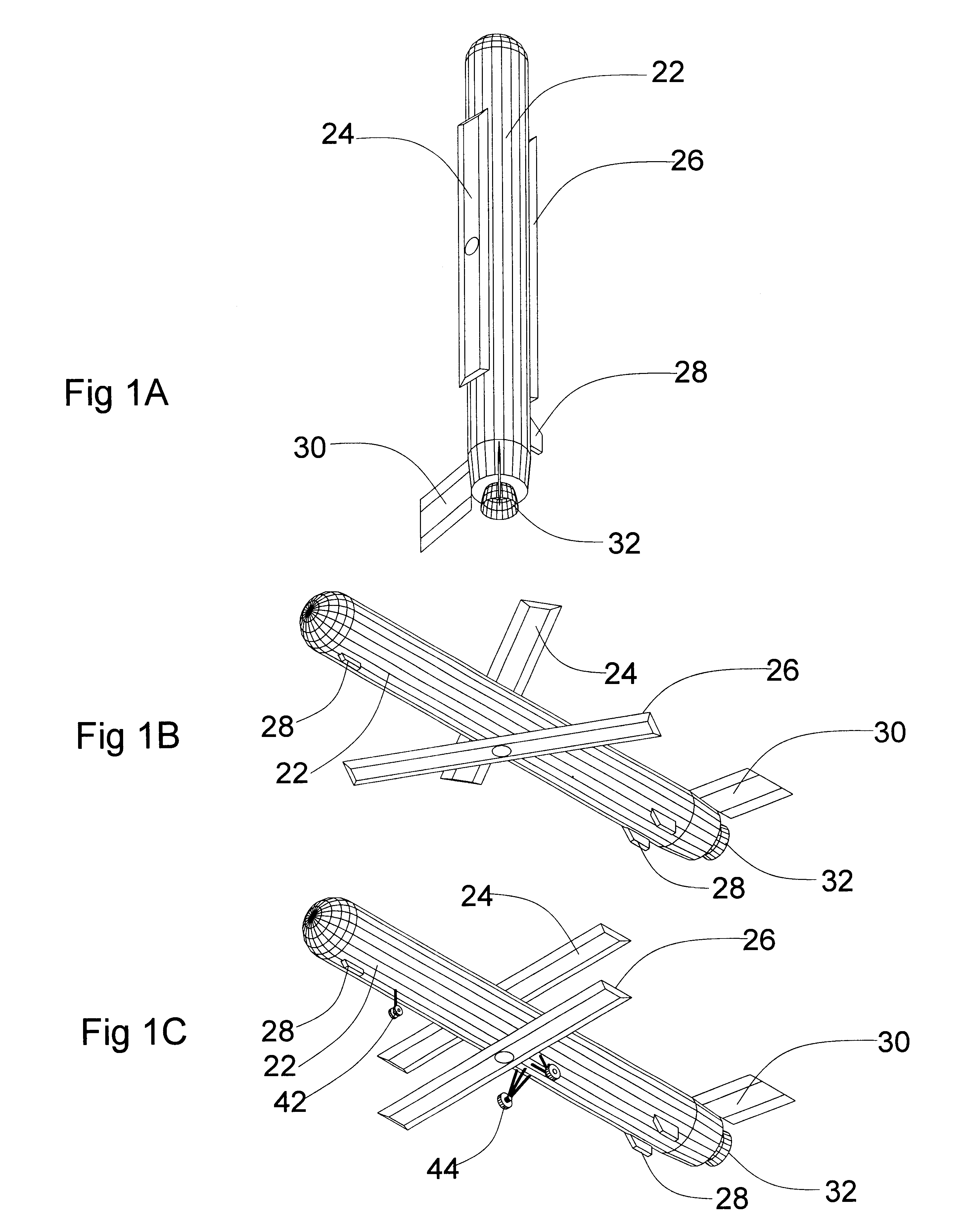
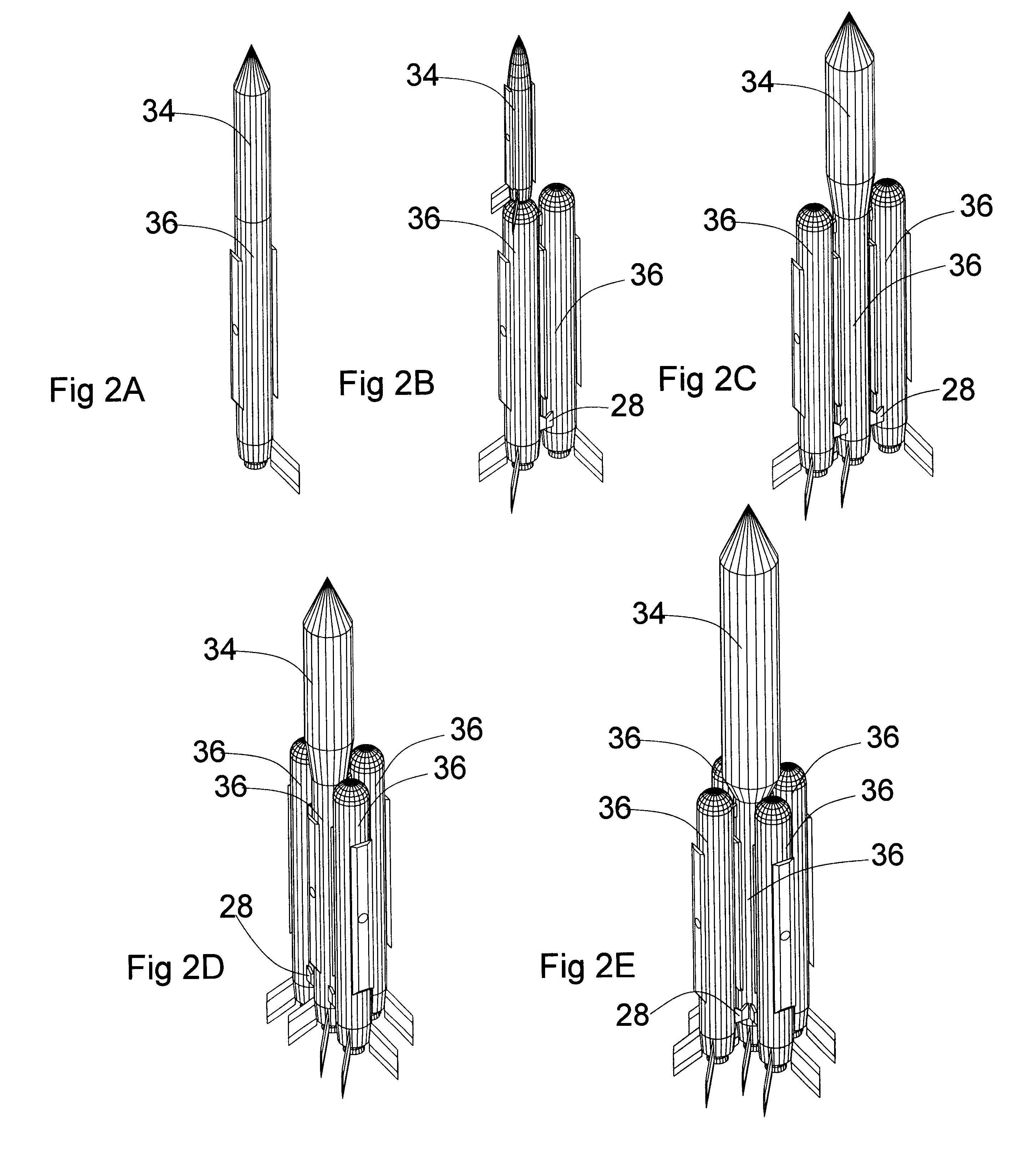
FIG. 1A to FIG. 2E show the preferred embodiment of a fly back booster based on the invention. FIG. 1A to FIG. 1C indicate how a fly back booster works, and FIG. 2A to FIG. 2E indicate how one or more fly back boosters form different launch configurations.

In FIG. 1A, a fly back booster is at vertical position and ready to launch payload either by installing upper stage(s) and payload on it or connecting it with other fly back boosters and / or other vehicle(s) to form different launch configurations for launch systems. As shown in the figure, it has two main wings, upper main wing 24 is rotatably mounted on the back of its fuselage 22 and lower main wing 26 is rotatably mounted at the belly of its fuselage 22. Both of the main wings are yawed to be generally parallel with the longitudinal axis of fuselage 22 so that the fuselage can get close to other fly back boosters and / or other vehicles from many directions and get connected with them. Two control surfaces 30 are i...


PUM


Abstract

A spacecraft such as a fly back booster or a reusable launch vehicle, or an aerospace plane has a fuselage and a set of scissors wings consisting of two main wings. Both of the main wings are rotatably mounted on the fuselage and can be yawed at opposite directions. If the spacecraft is launched vertically, both of its main wings can be yawed to be generally parallel with its fuselage so that it can connect with other vehicle or vehicles to form different launch configurations. When the spacecraft or aerospace plane is flying in the air, landing, or taking off horizontally, it can yaw both of its main wings in opposite directions to maximize its lift-to-drag ratio by optimizing the yaw angle of the main wings according to flying conditions. It can also produce desired aerodynamic characteristics such as forming a high drag configuration by adjusting the yaw angle of its main wings. The scissors wings can be used on a spacecraft that is launched vertically on the ground, or a spacecraft that is carried to the air and launched in the mid-air, or a spacecraft that takes off horizontally like an aircraft or glider. The scissors wings can also be used on an aerospace plane.

Description

FEDERALLY SPONSORED RESEARCHNot ApplicableREFERENCE TO SEQUENCE LISTING, A TABLE, OR A COMPUTER PROGRAM LISTING COMPACT DISK APPENDIXNot Applicable1. Field of InventionThe invention relates in general to spacecraft and aerospace plane, in particular, to fly back boosters that can be recovered after use, to reusable launch vehicles that can go to and come back from Earth orbits, and to aerospace vehicles that can fly at hypersonic speed in the air and / or go to and come back from Earth orbits.2. Description of Prior ArtFly Back BoosterMost existing designs of fly back boosters are based on configurations of fixed wings with fixed sweep angles. These fixed wings stick out from the fuselages of fly back boosters thus limit the flexibility of forming different launch configurations by connecting a fly back booster with other fly back booster(s) and / or other vehicle(s). In addition, most designs of fixed-wing fly back boosters choose wings with low aspect ratio. A fly back booster with wi...

Claims


Application Information

Patent Timeline
Patent Type & Authority Patents(United States)
IPC IPC(8): B64G1/14B64C39/08B64G1/00B64C3/40B64C39/00B64C3/00B64C3/56
CPCB64C3/40B64C3/56B64C39/08B64G1/14B64G1/002Y02T50/145Y02T50/10
Inventor CHEN, ZHUO
Owner CHEN ZHUO
Why Eureka
Try Eureka