Binary machine tool holder

a technology for machine tools and holder, which is applied in the field of holder for machine tools, can solve the problems of relative high cost of actuation (heating) equipment and pose safety concerns, and achieve the effects of reducing cost, reducing elasticity, and reducing the cos

Inactive Publication Date: 2004-06-15
COMMAND TOOLING SYST
View PDF14 Cites 21 Cited by
  • Summary
  • Abstract
  • Description
  • Claims
  • Application Information

AI Technical Summary

Benefits of technology

In general terms, the invention is a holder for a cutting or forming tool that has two distinct phases. In the first phase, the tool is held with sufficient mechanical interaction between the holder and the tool for the tool to perform its intended purpose on a workpiece. In the second phase, the holder releases the tool sufficiently for it to be rapidly removed, such as by an automated apparatus. The holder may be repeatedly switched between the two phases by application of an external agent, such as by an actuation system of some type (e.g., a heating or cooling system, or a system for applying an electromagnetic field), without degradation of performance (e.g., loss of elasticity). As compared to conventional shrink fit tool holders, the invention provides reduced cost, safer actuation, and reduced time to exchange tools, all of which improve the cost effectiveness of the system.

Problems solved by technology

This approach involves relatively expensive actuation (heating) equipment, poses safety concerns due to the high temperatures involved for most industrial quality tools having relatively large amounts of metal, and is slower than desired.

Method used


Image

  • Binary machine tool holder
  • Binary machine tool holder
  • Binary machine tool holder

Examples


Embodiment Construction

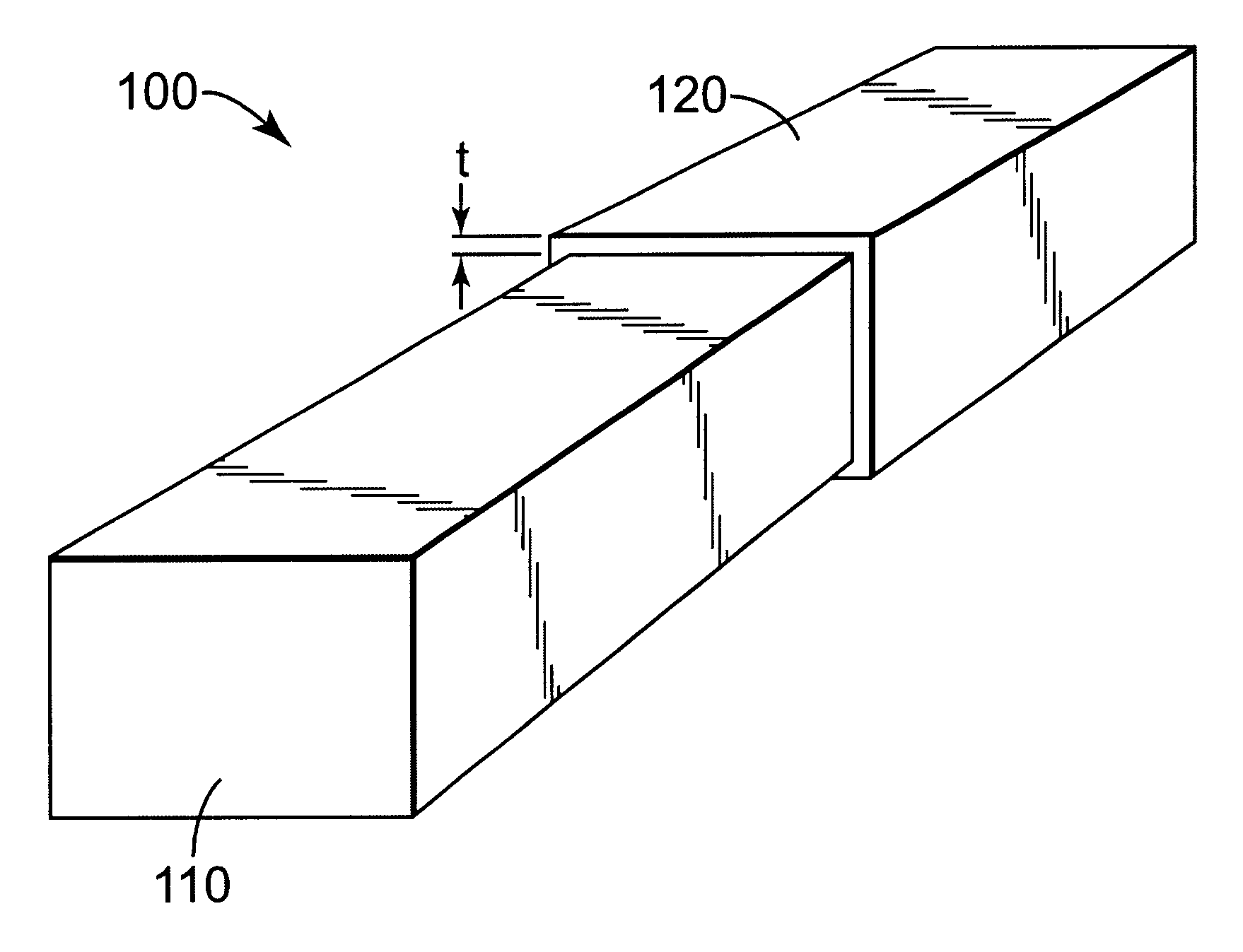
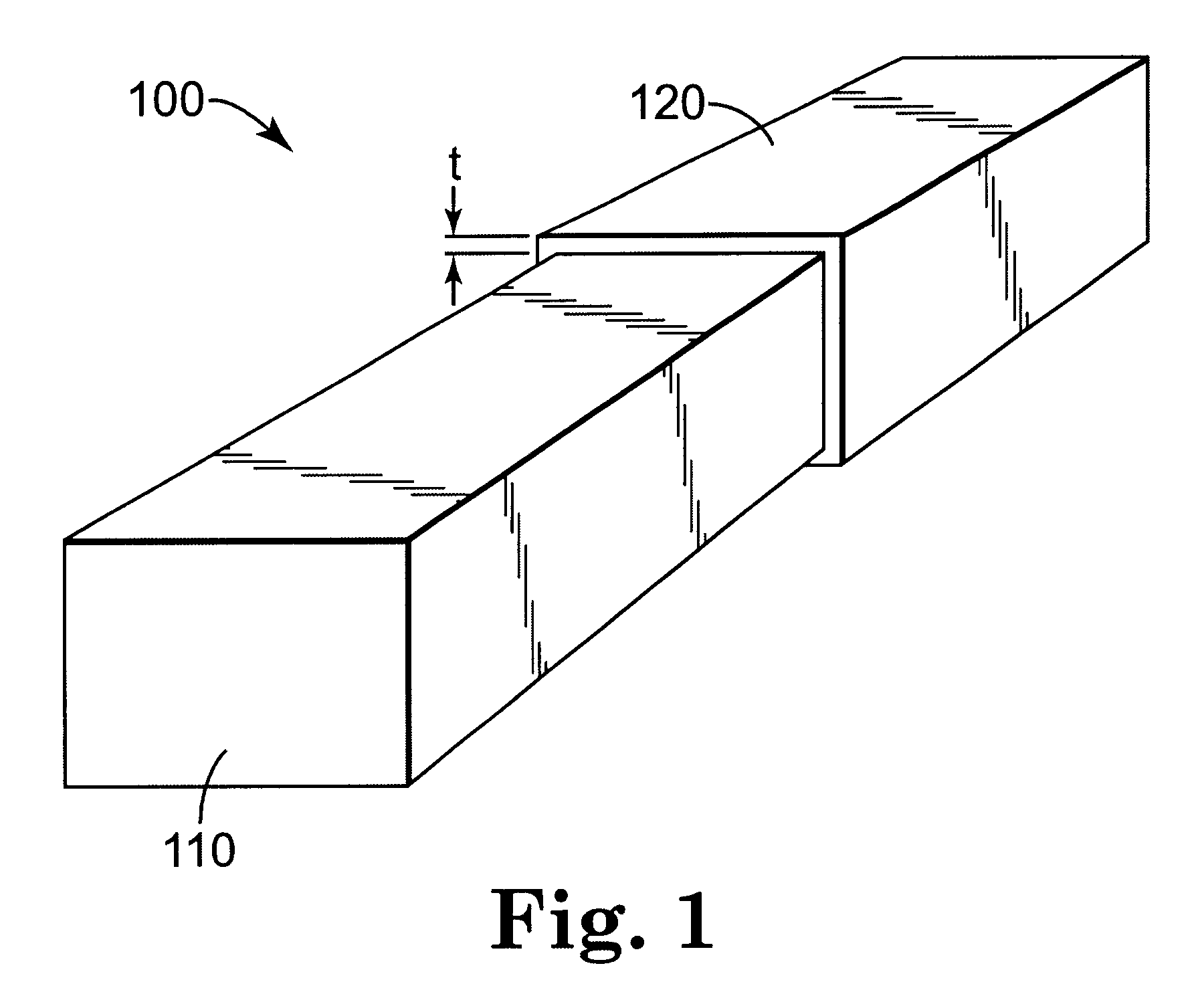
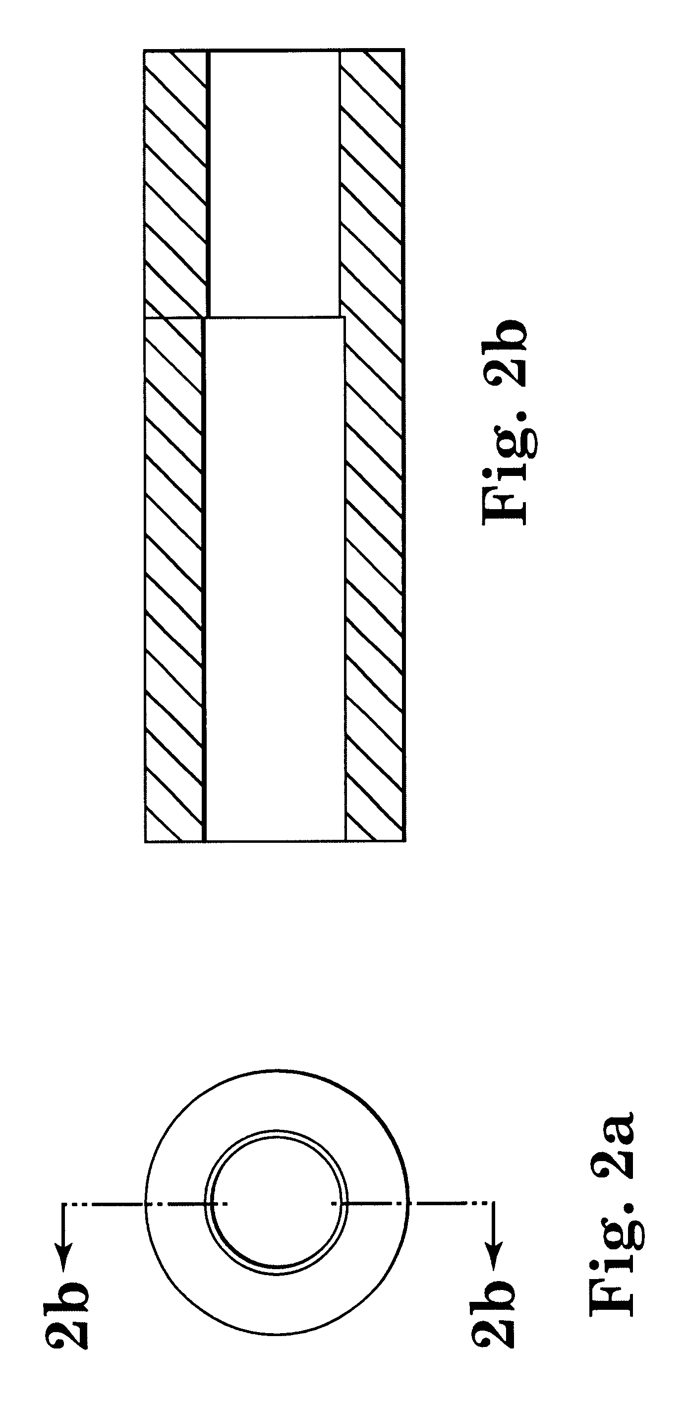
Three prototypes of a tool holder suitable for CNC applications were constructed as shown in FIGS. 2 and 3. FIG. 2 shows a hollow cylindrical sleeve of SMA material designed to fit within the prototype tool holder of FIG. 3. The SMA piece was designed to hold a conventional cutting or forming tool (not shown) having a conventionally sized cylindrical shaft. FIG. 3 shows a modified version of a generic tool holder similar to collet chucks and the like available from Command Tooling Systems of Ramsey, Minn. USA. Thus, together, the prototype pieces form a binary tool holder for CNC applications.

A nickel-titanium SMA commonly designated as NiTiNOL was employed. The SMA pieces were formed from one inch hot rolled bar stock, having a composition of 56% nickel and 44% titanium, and an austenitic finish temperature of 0 Celsius. The stock was water jet cut to a rough length and then machined to final dimensions by using a lathe to face off the ends and to drill out the inside. This process...


PUM

PropertyMeasurementUnit
diameteraaaaaaaaaa
diametersaaaaaaaaaa
austenitic finish temperatureaaaaaaaaaa

Abstract

A tool holder having two distinct phases, a first phase in which the tool is held in an interference fit with sufficient mechanical interaction between the two for the tool to be rotated at high speed and perform its intended purpose on a workpiece, and a second phase in which the tool is sufficiently released from the interference fit to be rapidly removed from the holder (as by an automated apparatus).

Description

This invention concerns holders for machine tools.Many cutting or forming tools must be held by a holder with sufficient mechanical interaction (e.g., static and dynamic stiffness, gripping strength, and the like) to enable the tool to perform its intended function on a workpiece as the holder and tool are moved (typically rotated), sometimes at high speed. In modern equipment, tools must be released from the tool holder and replaced with new tools by automated systems. For maximum productivity and cost effectiveness, this process should occur as quickly as possible.One existing type of tool holder employs a shrink fit, in which the tool holder is heated so that it expands enough to accommodate the tool, and then actively or passively cooled so that it will contract and thus hold the tool during use. This approach involves relatively expensive actuation (heating) equipment, poses safety concerns due to the high temperatures involved for most industrial quality tools having relativel...

Claims


Application Information

Patent Timeline
Patent Type & Authority Patents(United States)
IPC IPC(8): B23B31/10B23B31/117
CPCB23B31/117B23B31/1179Y10T407/27B23B2228/56Y10T407/22B23B2228/16
Inventor KEEFE, WILLIAM RJOHNSON, RANDOLF N.LODERMEIER, CHRISTOPHER M.NESS, PETER J.ROWELL, BRADLEY E.SHANNON, MARK A.NIETHAMMER, JOHN
Owner COMMAND TOOLING SYST
Why Eureka
Try Eureka