Method for producing amorphous alloy ribbon, and method for producing nano-crystalline alloy ribbon with same

a technology of amorphous alloy ribbon and nano-crystalline alloy, which is applied in the field of producing amorphous alloy ribbon and producing nano-crystalline alloy ribbon with same, can solve the problems of embrittlement and crystallization of formed amorphous alloy ribbon, extreme difficulty in handling, and new irregular shape of serrated edge portions

Inactive Publication Date: 2004-06-15
HITACHI METALS LTD
View PDF13 Cites 37 Cited by
  • Summary
  • Abstract
  • Description
  • Claims
  • Application Information

AI Technical Summary

Benefits of technology

Accordingly, an object of the present invention is to provide a method for continuously producing an amorphous alloy ribbon having improved surface conditions on a side in contact with a cooling roll and excellent edge shapes, free from embrittlement and crystallization.

Problems solved by technology

However, in a production experiment using a mass-production-scale apparatus, it was found that as the casting time passed, there arose the problems of embrittlement and crystallization in the formed amorphous alloy ribbon that were not observed in the short casting process, though the surface conditions of the amorphous alloy ribbon was improved by the supply of a CO.sub.2 gas.
In addition to these problems, it has also be found that a new problem of serrated irregular shapes in their edge portions takes place.
At this time, if the ribbon had a serrated irregular shape in its edge portions, the edge portion of the ribbon engages a reel, resulting in extreme difficulty in handling.
The irregular shape of the ribbon in its edge portions also poses inconveniences in the production of a wound core.
In this case, too, if the ribbon had a serrated irregular shape in its edge portions, the ribbon engages the abutting plate, thereby making the production of a wound core difficult.
If the ribbon were brittle, breakage, cracking, etc. would be likely to occur in the production of wound cores and laminated cores.
In addition, if the ribbon contains coarse crystals, it would have large crystal magnetic anisotropy, resulting in the deterioration of its soft magnetic properties.
Further, if an amorphous alloy ribbon having coarse crystals were heat-treated at a temperature equal to or higher than the crystallization temperature of the alloy, the resultant nano-crystalline alloy ribbon would have deteriorated soft magnetic properties.

Method used


Image

  • Method for producing amorphous alloy ribbon, and method for producing nano-crystalline alloy ribbon with same
  • Method for producing amorphous alloy ribbon, and method for producing nano-crystalline alloy ribbon with same
  • Method for producing amorphous alloy ribbon, and method for producing nano-crystalline alloy ribbon with same

Examples


examples 1 and 2

, COMPARATIVE EXAMPLES 1-4

Production and Evaluation of Amorphous Alloy Ribbon

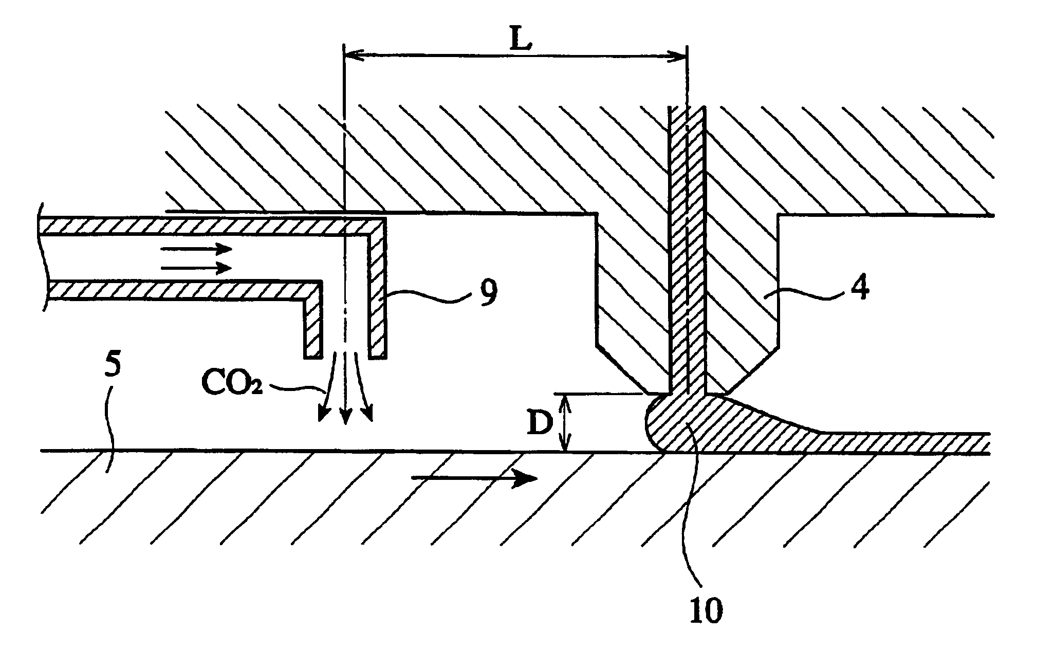
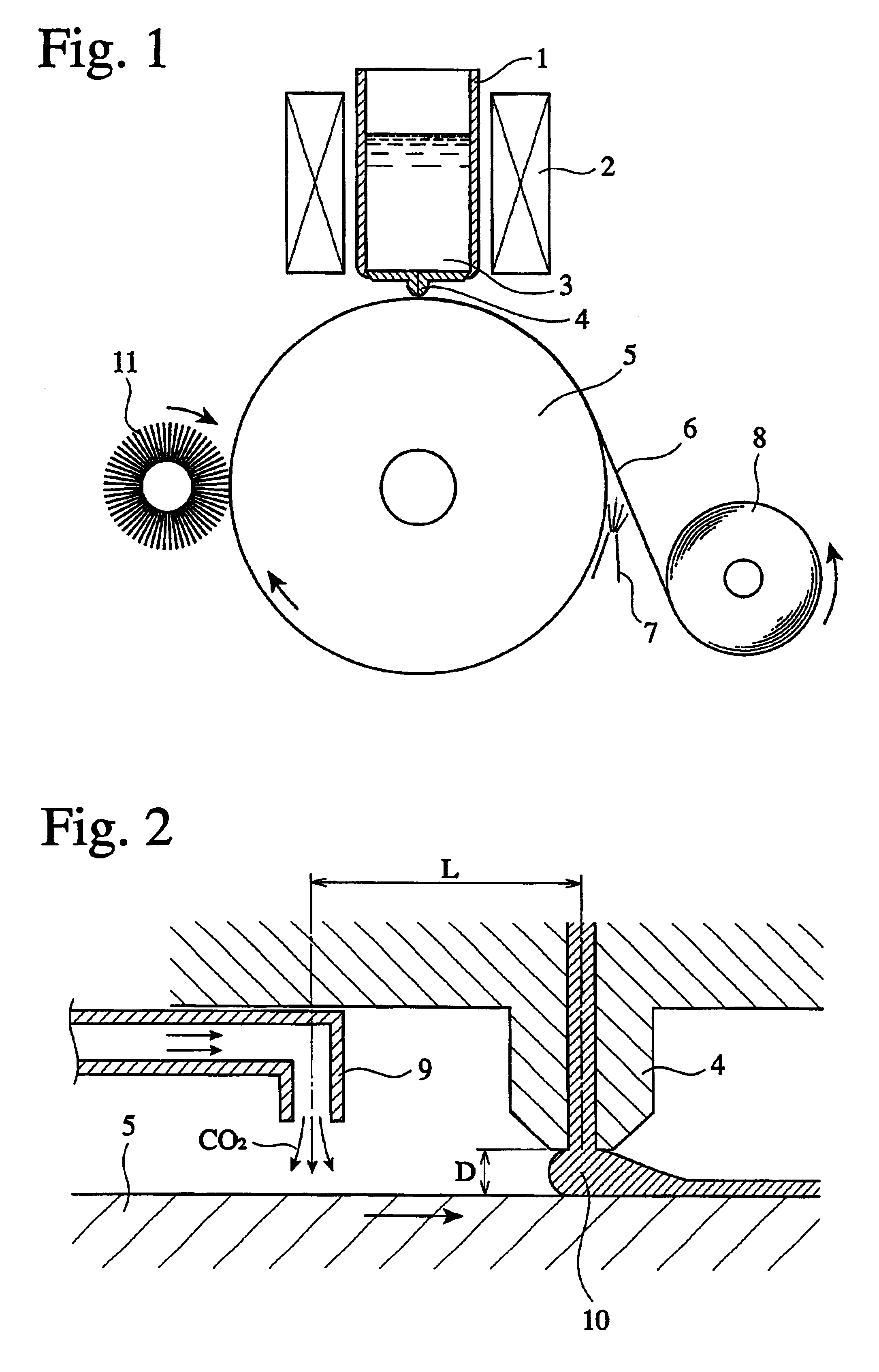
An ingot of an Fe-based alloy having a composition of Cu.sub.1 Nb.sub.2.5 Si.sub.13.5 B.sub.7 Fe.sub.bal. by atomic % was introduced into a crucible 1 shown in FIG. 1, and melted by induction heating by a high-frequency coil 2. The resultant alloy melt 3 was ejected onto a cooling roll 5 made of a Cu--Be alloy and rapidly quenched under the conditions shown in Table 1 below, to form an amorphous alloy ribbon 6 of EXAMPLE 1 having a width of 30 mm and a thickness of 19 .mu.m.

As shown in FIG. 1, the resultant amorphous alloy ribbon 6 was caused to peel off from the cooling roll 5 by supplying a nitrogen gas from a nozzle 7 onto the cooling roll 5 in an opposite direction to the rotation direction of the cooling roll 5, and a reel 8 having a permanent magnet embedded therein and rotating in an opposite direction to the rotation direction of the cooling roll 5 was brought close to the cooling roll 5 to wind the...

examples 3 and 4

, COMPARATIVE EXAMPLES 5-8

An ingot of an alloy having a composition of 9 atomic % of Si W and 13 atomic % of B, the balance being substantially Fe, was introduced into a crucible 1 shown in FIG. 1 and melted by induction heating by a high-frequency coil 2. The resultant melt 3 was ejected onto the cooling roll 5 made of a Cu--Cr alloy and rapidly quenched to produce an amorphous alloy ribbon 6 having a width of 40 mm and a thickness of 20 .mu.m under the conditions shown in Table 4.

Taken as samples were amorphous alloy ribbon portions obtained when 1 and 10 minutes, respectively, passed from the start of casting. The samples of EXAMPLE 3 and COMPARATIVE EXAMPLES 5 and 6 were ribbon portions obtained when 1 minute passed from the start of casting, and the samples of EXAMPLE 4 and COMPARATIVE EXAMPLES 7 and 8 were ribbon portions obtained when 10 minutes passed from the start of casting.

Incidentally, the grinding of the cooling roll 5 was carried out by rotating a brush 11 in the same...

examples 5-7

Each ingot of alloys having compositions shown in Table 8 was introduced into a crucible 1 shown in FIG. 1, and melted by induction heating by a high-frequency coil 2. Each of the resultant alloy melts 3 was ejected onto a cooling roll 5 made of a Cu--Be alloy and rapidly quenched to produce an amorphous alloy ribbon 6 having a width of 30 mm and a thickness of 22 .mu.m under the conditions shown in Table 7. The casting of the amorphous alloy ribbon was repeated 10 times. In the production process of the ribbon with a CO.sub.2 gas supplied, the grinding of the cooling roll 5 was carried out by rotating a brush 11 in the same direction as the cooling roll 5. The winding method of the resultant ribbon was the same as in EXAMPLE 1.

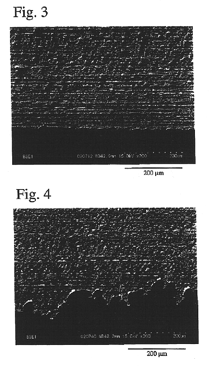
Each of the resultant ribbons was measured with respect to an average surface roughness Ra according to JIS B 0601 both on a freely solidified surface and on a side in contact with the cooling roll 5. Also, a 180.degree. bending test was carried out according...


PUM

PropertyMeasurementUnit
surface roughnessaaaaaaaaaa
lengthaaaaaaaaaa

Abstract

An amorphous alloy ribbon free from embrittlement and crystallization and having excellent surface conditions and shape in edge portions is produced by (a) preparing an alloy melt having a composition comprising 13 atomic % or less of B and 15 atomic % or less of at least one selected from the group consisting of transition elements of Groups 4A, 5A and 6A, the balance being substantially Fe; (b) ejecting the alloy melt at a temperature from the melting point of the alloy +50° C. to the melting point of the alloy +250° C. through a nozzle onto the cooling roll rotating at a peripheral speed of 35 m / second or less, a distance between a tip end of the nozzle and the cooling roll being 200 mum or less; (c) starting to supply a gas based on CO2 to the alloy melt after the surface temperature of the cooling roll has become substantially constant; and (d) grinding the cooling roll while supplying the gas based on CO2.

Description

The present invention relates to a method for producing an amorphous alloy ribbon having excellent surface conditions and shape in edge portions, and a method for producing a nano-crystalline alloy ribbon using such an amorphous alloy ribbon.PRIOR ARTLiquid-quenching methods are widely known as methods for producing amorphous alloy ribbons for use in magnetic cores, magnetic shields, etc. The liquid-quenching methods include a single roll method, a double roll method, a centrifugal method, etc., and preferable among them from the aspect of productivity and the maintenance of an apparatus is a single roll method in which a molten metal is supplied onto a cooling roll rotating at a high speed and rapidly quenched to form an alloy ribbon.FIG. 1 shows one example of apparatuses for carrying out the single roll method. An alloy ingot in a crucible 1 is melted by a high-frequency coil 2, and the resultant alloy melt 3 is ejected through a nozzle 4 onto a cooling roll 5 rotating at a high ...

Claims


Application Information

Patent Timeline
Patent Type & Authority Patents(United States)
IPC IPC(8): C22C33/00C22C45/00C22C45/02
CPCC22C33/003C22C45/02
Inventor SUNAKAWA, JUNBIZEN, YOSHIONAGAO, MICHIHIRO
Owner HITACHI METALS LTD
Why Eureka
Try Eureka