Method and apparatus for spatial-shift wavelength multiplexing in communication systems

Inactive Publication Date: 2004-07-13
LUCENT TECH INC
View PDF10 Cites 3 Cited by
  • Summary
  • Abstract
  • Description
  • Claims
  • Application Information

AI Technical Summary

Problems solved by technology

The fundamental problem associated with most diffraction grating routers is that imaging through a diffraction grating creates a linear shift of the focal spot as a function of wavelength, a result which is conflict with the goal of achieving a segmented, flat-topped passband that is inherently a non-linear function.
This arrangement can produce a flat passband, but since the insertion loss scales linearly with the number of wavelength channels, it is not generally regarded as suitable for large channel count WDM or DWDM systems.
Array waveguide routers (AWR), sometimes referred to as "Dragone" routers, ca

Method used


Image

  • Method and apparatus for spatial-shift wavelength multiplexing in communication systems
  • Method and apparatus for spatial-shift wavelength multiplexing in communication systems
  • Method and apparatus for spatial-shift wavelength multiplexing in communication systems

Examples


Embodiment Construction

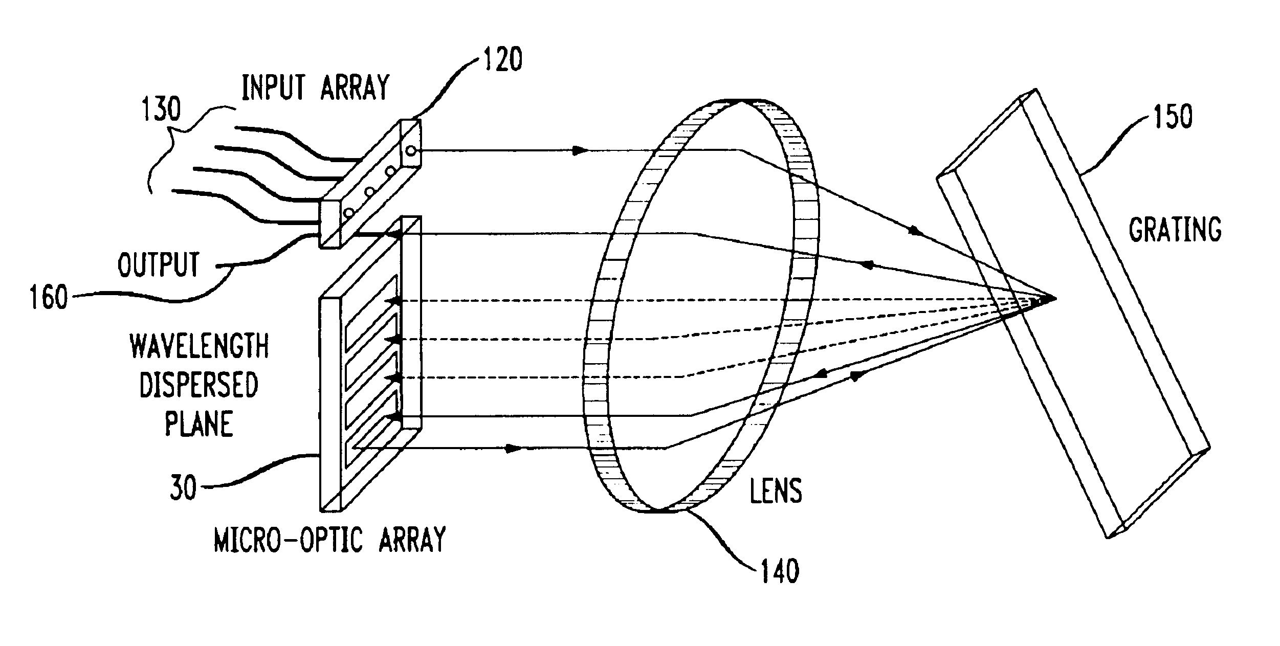
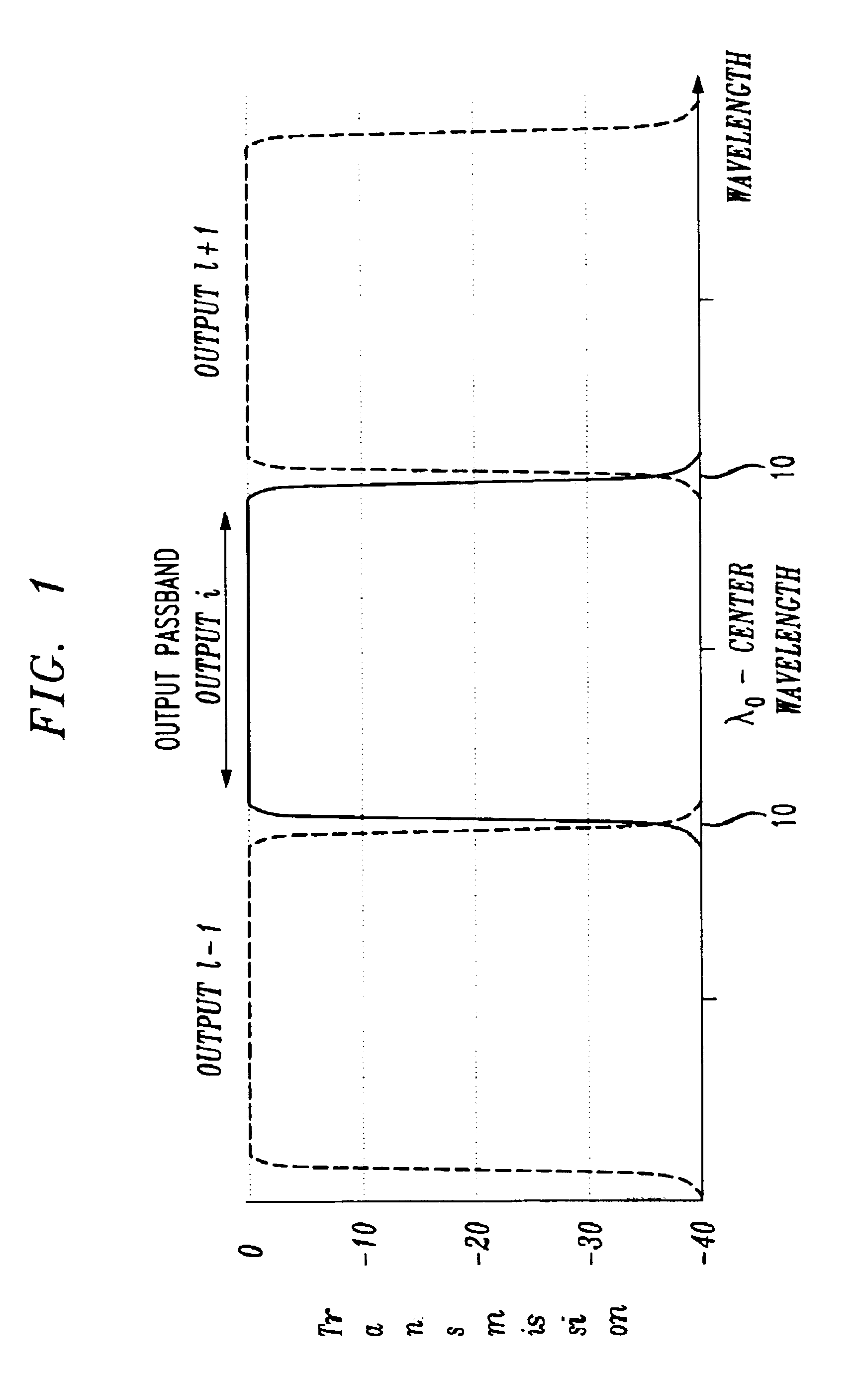
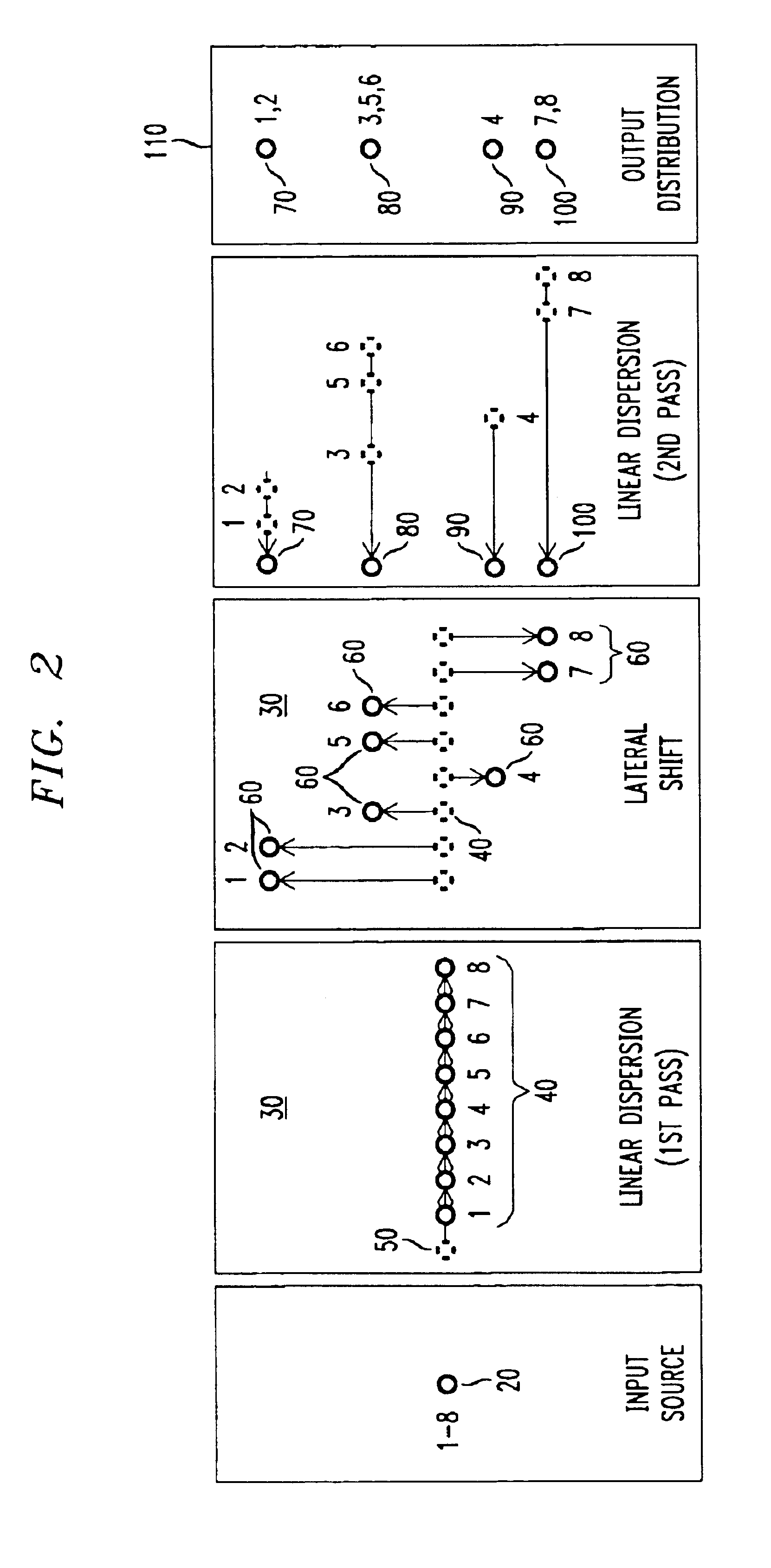
Referring now to the drawings, FIG. 2 shows conceptually the various shapes that a spectrum of light undergoes in accordance with the present invention to produce a spatially-shifted, multiplexed spectrum with an optimum passband depicted generally in FIG. 1, which is a non-linear response. An input source 20 transmits a spectrum containing a plurality of signals. In FIG. 2, the spectrum is shown by way of example as including eight discrete wavelengths, although it will be recognized by those skilled in the art that any number of discrete signals may be transmitted by input source 20. The spectrum is preferably transmitted by an optical fiber, but may also be transmitted by other equivalent input sources such as a lens, mirror, or other optical device adapted to carry multiplexed signals having a spectrum. The signal is imaged onto an intermediate image plant 30 wherein the individual wavelength signals are linearly dispersed into discrete regions in a substantially linear pattern ...


PUM


Abstract

Methods and apparatus for spatially-shifting and multiplexing optical signals for transmission in a wavelength division multiplexed or dense wavelength division multiplexed optical communication system linearly disperse the optical signals and then spatially, laterally shift the signals. The spatially shifted, dispersed signals are thereafter re-imaged to remove the linear dispersion so that the spatially shifted signals can then be transmitted through the optical communication system. The spatially-shifted, multiplexed signals have a flat passband with sharp transition points so that the transmitted signals are routed through the optical communication system with low loss and high integrity.

Description

1. Field of the InventionThe present invention relates generally to methods and systems for spatial-shift, wavelength multiplexing of optical signals in an optical communication system. More specifically, the invention relates to methods and systems for routing optical signals through an optical communication system by spatially shifting the signals and dispersing the signals into discrete regions onto an optical plane.2. Description of the Related ArtWith the advent of high-speed wavelength division multiplexed (WDM) and dense wavelength division multiplexed (DWDM) systems over the last few years, optical routers in such systems have played an increasingly significant role for routing multi-wavelength, highly dispersible signals through the system. Wavelength multiplexers include various designs which produce different kinds of output signals for particular applications. Generally speaking, the desired passband response of a WDM router is a flat, uniform response over a pre-determi...

Claims


Application Information

Patent Timeline
IPC IPC(8): G02B6/34
CPCG02B6/4215
Inventor FORD, JOSEPH EARLNEILSON, DAVID THOMAS
Owner LUCENT TECH INC
Why Eureka
Try Eureka