Solid phase welding

a solid phase welding and welding technology, applied in the direction of soldering apparatus, manufacturing tools, auxillary welding devices, etc., can solve the problems of affecting the repair process, the repair area must be continuously monitored, and the leading edge of the aircraft wing to crack, etc., to achieve the effect of improving the repair process and improving the repair process

Inactive Publication Date: 2004-07-27
AIRBUS OPERATIONS LTD
View PDF17 Cites 8 Cited by
  • Summary
  • Abstract
  • Description
  • Claims
  • Application Information

AI Technical Summary

Benefits of technology

The applicants have discovered that solid phase welding may provide a suitably strong weld, and can be used as a method of repair of a crack in an aircraft skin while not jeopardising the properties required throughout the material to provide optimum safety, particularly when the repaired region is subjected to the stresses normally associated with an aircraft during flight, take-off and landing.
The friction stir welding process has many advantages over traditional welding techniques. Most notably, the welded material undergoes very little distortion or shrinkage during the process. The process does not produce any fumes, sparks, porosity or spatter. The process can be repeatedly carried out, efficiently and effectively, on materials that are known as being difficult to weld (such as, for example, 2000 and 7000 series aluminium alloys). Furthermore, the process is energy efficient and suitable for automation. The welding tool is generally non-consumable, and can often be used for up to 1000 m of weld length during its lifetime, before requiring replacement. No filler or gas shielding is required. The mechanical properties of the welds produced are also substantially improved. Friction stir welding provides ease of repair and good post-repair benefit, while avoiding the disadvantages of increased fatigue and stress to the repaired area, due to the fact that the welding is carried out in the solid phase and at a low temperature.
Preferably, the method comprises positioning the solid phase welding tool so as to extend part way through the thickness of the aircraft skin. In that way, the position of the tool effectively controls the depth of the weld.
According to a second aspect of the invention there is provided solid phase welding apparatus comprising a base, a support for a solid phase welding tool movable on the base, and means for mounting the apparatus on a workpiece to be welded, the movement of the support on the base enabling the tool to be moved relative to the workpiece as the tool is operated to produce a weld.

Problems solved by technology

It is not unusual for cracks to occur in the skin of a leading edge of an aircraft wing.
The disadvantage with such a method is that the repaired area must be continually monitored and frequently inspected to make sure the repaired area is always capable of withstanding the stresses and strains on the aircraft wing when the aircraft is in service.
Traditionally, welding has not been considered as a suitable method of repair of an aircraft skin.
This, in turn, results in increased fatigue in the repaired area, as well as increased crack propagation life.
Furthermore, it is extremely difficult to avoid distortion of the thin light alloy material during the welding process.
Frictional heat is generated by the welding tool which plasticises the material directly under the tool head.
Although friction stir welding is known, per se, as a technique, for joining two metal plates, or two sides of a metal plate, it has never been used before as a method of repairing crack damage in an aircraft skin.
Moreover, it has not been considered as a possible method of repair of crucially important components such as an aircraft wing.
This is because general welding techniques, particularly on thin light alloy skins used on aircraft have been problematic due to the increased fatigue of the repaired section once it has been subjected to heat, and the material itself has undergone melting.
Previously, solid phase welding apparatus, and in particular friction stir welding, apparatus has been of a non-portable kind because of problems of workpiece clamping and access requirements.
As the solid phase welding is a low temperature process, safety precautions regarding the production of heat and sparks are not as stringent as for general welding techniques.

Method used


Image

  • Solid phase welding
  • Solid phase welding
  • Solid phase welding

Examples


Embodiment Construction

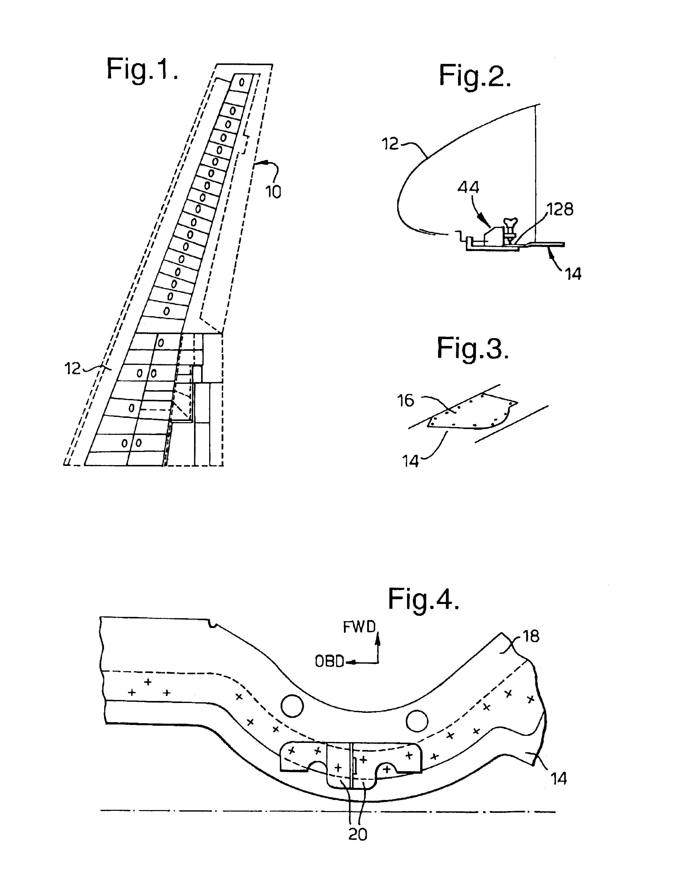
Referring to FIGS. 1, 2 and 3, a wing 10 has a leading edge 12 formed in known manner from light alloy sheet material. The leading edge 12 has a lower skin 14 as shown in FIGS. 2 and 3, the lower skin 14 being provided with an access panel 16 which is held in position by releasable fasteners of known kind.

Looking at FIG. 4, the lower skin 14 carries an edge member 18 and landing plates 20 used for the mounting of components (not shown). The edge member 18 and landing plates 20 are attached to the skin 14 by rivets in known manner.

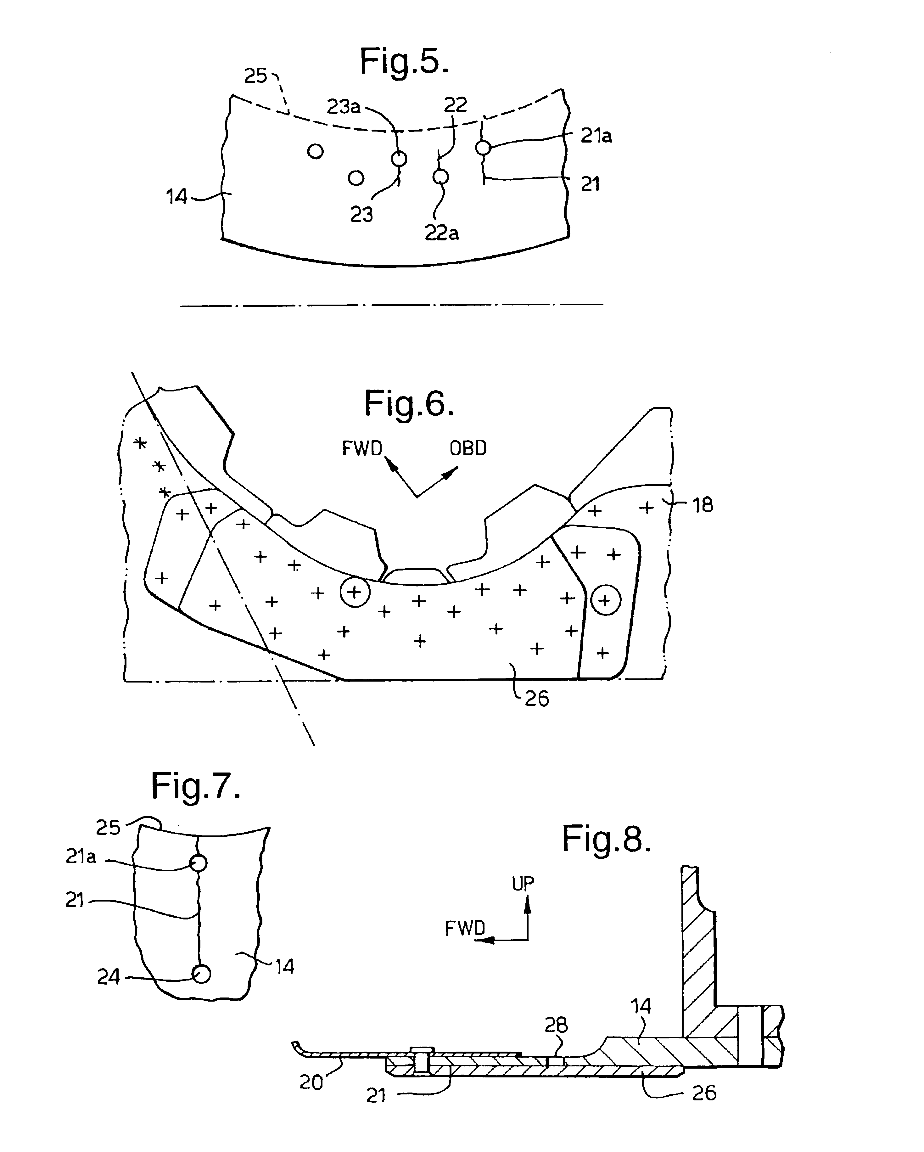
When the aircraft is in service, it is not unusual for cracks to appear in the material forming the leading edge and FIG. 5 illustrates the way in which cracks 21, 22 and 23 have formed through three holes indicated at 21a, 22a and 23a.

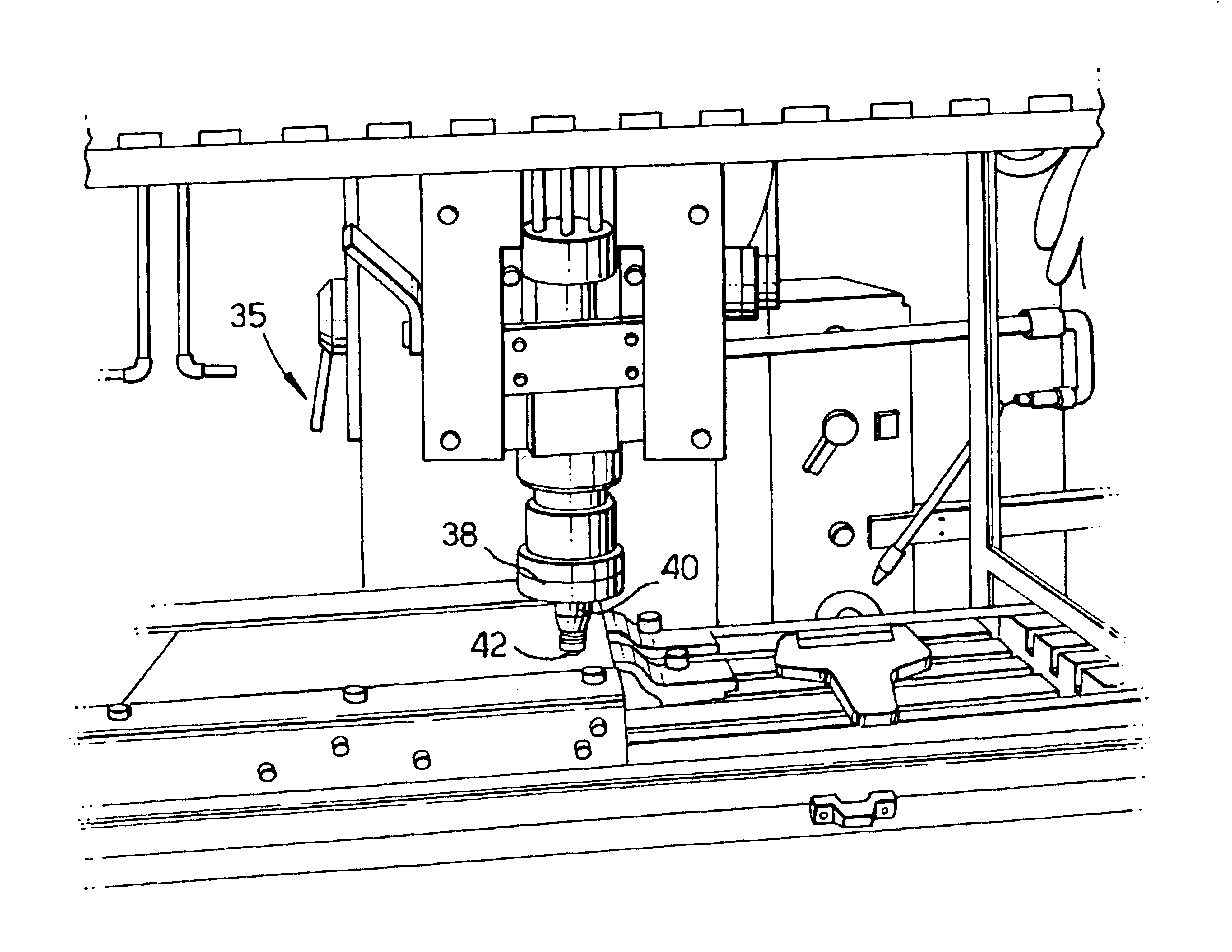
FIGS. 6 and 7 serve to show the way in which the lower skin 14 can be repaired when cracks occur as shown in FIG. 5. The rivets holding the edge member 18 and landing plates 20 in position are drilled away so as to leave the ...


PUM

PropertyMeasurementUnit
thicknessaaaaaaaaaa
weld lengthaaaaaaaaaa
depthaaaaaaaaaa

Abstract

The method comprises introducing a tip of a solid phase welding tool between adjacent surfaces of a crack formed in an aircraft skin. The tool is then operated to produce a friction stir weld so as to weld the adjacent surfaces together and thereby repair the crack. Apparatus for performing the method comprises a base having carriage thereon, the arm being pivotally mounted on the carriage and supporting the friction stir welding tool. The position of an arm can be adjusted by a screw which drives the rotating tip of friction stir welding tool into the crack to be repaired. The carriage is then moved along the base to draw the tip along the crack. The apparatus is portable and is particularly useful for repairing a cracked skin on an aircraft.

Description

1. Field of the InventionThe present invention relates to solid phase welding. Primarily, the invention is concerned firstly with a method of repairing an aircraft skin such as an aerofoil by solid phase welding and, secondly, with a solid phase welding apparatus2. Discussion of Prior ArtIt is of vital importance that any damage incurred by an aerofoil of an in-service aircraft is repaired immediately and effectively. It is not unusual for cracks to occur in the skin of a leading edge of an aircraft wing. The leading edge of an aircraft wing may be made from a flat sheet of suitable light alloy such as 2024 aluminium alloy of about 3 mm thickness.The current method of repair of such leading edge cracks involves preventing the crack from extending any further by drilling a hole at each of its ends and then reinforcing the area in the immediate vicinity of the crack, by fastening a plate or bracket over the crack to reduce the level of stress incurred in that area. The disadvantage wi...

Claims


Application Information

Patent Timeline
Patent Type & Authority Patents(United States)
IPC IPC(8): B23K20/12B64F5/00
CPCB23K20/1265B23K20/1285B23K20/129B64F5/0081B23K2201/006B64F5/40B23K2101/006
Inventor SHEPHERD, GERALD E
Owner AIRBUS OPERATIONS LTD
Why Eureka
Try Eureka