Long-pulse pulse power system for gas discharge laser

a laser and long-pulse technology, applied in the field of long-pulse pulse power system for gas discharge lasers, can solve the problems of deteriorating discharge quality and efficiency, unable to double the pulse duration, and ineffective change of l or

Inactive Publication Date: 2004-08-24
CYMER INC
View PDF9 Cites 65 Cited by
  • Summary
  • Abstract
  • Description
  • Claims
  • Application Information

AI Technical Summary

Problems solved by technology

Any change in L or C is not very effective since pulse duration only increases to the square root.
Both measures deteriorate the discharge quality and efficiency.
Therefore a doubling of the pulse duration will not be possible with a simple LC circuit.
Unfortunately, spiker-sustainer circuits are not applicable to lithography lasers.
KrF and ArF discharges use F.sub.2 as the halogen donor, which makes disc

Method used


Image

  • Long-pulse pulse power system for gas discharge laser
  • Long-pulse pulse power system for gas discharge laser
  • Long-pulse pulse power system for gas discharge laser

Examples


Embodiment Construction

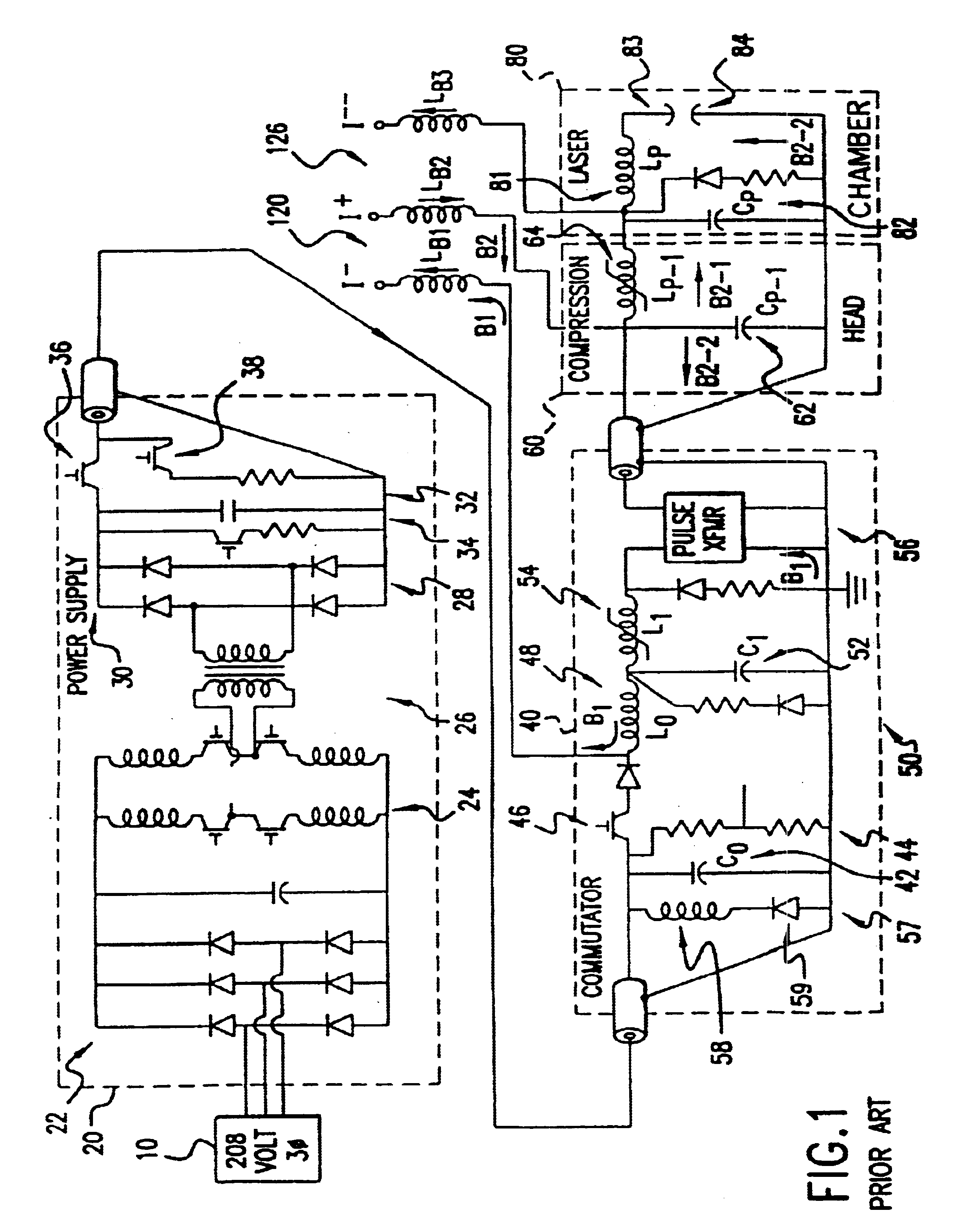
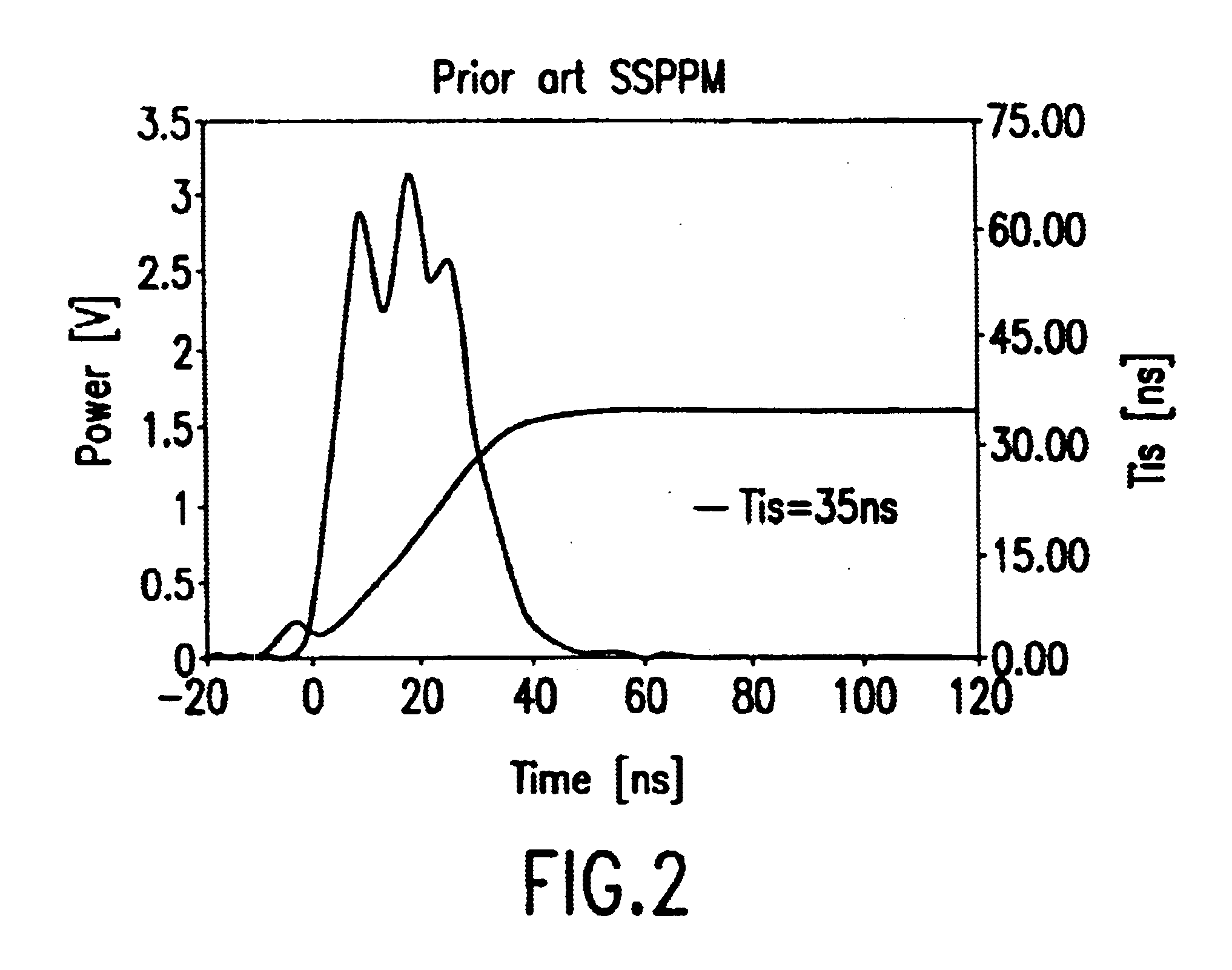
A first preferred embodiment of the present invention can be described by reference to FIG. 3. This embodiment is exactly the same as the system described in FIG. 1 through pulse transformer 56. The improvements of the present invention can be described by comparing FIG. 3 to FIG. 2 which shows the main components of the prior art pulse power system of FIG. 1 which are downstream of the pulse transformer.

In this embodiment, long pulses are generated by means of a double pulse excitation circuit. The individual pulses have high gain to allow line-narrowing and are timed in close succession to act as a single pulse. The basic circuit is a variation of the spiker-sustainer circuit. However, the energy stored in the spiker circuit is increased sufficiently to generate a spiker lasing pulse. The second pulse is generated by the sustainer circuit, with a time constant reduced to provide higher gain relative to classical sustainer circuits. The circuits are balanced to provide roughly equa...


PUM


Abstract

A long pulse power system for gas discharge lasers. The system includes a sustainer capacitor for accepting a charge from a high voltage pulse power source. A peaking capacitor with a capacitance value of less than half the sustainer capacitance provides the high voltage for the laser discharge.

Description

Pulse Power SystemsPulse power electrical systems are well known. One such system is described in U.S. Pat. No. 5,142,166 issued to Birx. That patent described a magnetic pulse compression circuit which shortens and amplifies an electrical pulse resulting from the discharge of a charge storing capacitor bank. The patent also describes a induction transformer for amplifying the pulse voltage.Another pulse power circuit is described in U.S. Pat. No. 5,729,562 issued to Birx, et al. which describes a pulse power system for a gas discharge laser and includes an energy recovery circuit for recovering electrical energy reflected from the laser electrodes.Gas Discharge Lithography LasersGas discharge lasers are well known and many of these lasers utilize pulse power systems such as those described in the two above-referenced patents to provide short high-voltage electrical pulses across the electrodes of the lasers. One such gas discharge laser is described in U.S. Pat. No. 4,959,840.Laser...

Claims


Application Information

Patent Timeline
IPC IPC(8): G03F7/20H03K3/57H03K17/80
CPCG03F7/70025G03F7/70041G03F7/70483G03F7/70558H03K3/57H03K17/80
Inventor HOFMANN, THOMASJOHANSON, BRUCE D.
Owner CYMER INC
Why Eureka
Try Eureka