
Hybrid alternator with an axial end retainer for permanent magnets

a technology of axial end retainer and alternator, which is applied in the direction of windings, magnetic circuit rotating parts, magnetic circuit shape/form/construction, etc., can solve the problems of affecting machine safety and efficiency, and achieve the effect of ensuring safe and efficient operation of rotating machines and avoiding excessive heating of elements

Inactive Publication Date: 2004-08-31
VALEO EQUIP ELECTRIC MOTEUR
View PDF8 Cites 37 Cited by
  • Summary
  • Abstract
  • Description
  • Claims
  • Application Information

AI Technical Summary

Benefits of technology

The invention is a rotating machine that combines the benefits of two types of machines: an alternator and an alternator / starter for motor vehicles. The machine has a stator surrounding a rotor with excitation coils and permanent magnets integrated into the rotor. The excitation coils are wound around salient poles cut out in the rotor's pack of metal plates. The retaining piece, which is a non-magnetic part, is designed to come into abutment with the magnets and has recesses for accommodating the excitation coils. The machine also includes cooling means for the coils, such as fan blades, and grooves for accommodating the wire of the excitation coils. The housings of the permanent magnets are closed at the outer periphery of the rotor to prevent excessive heating. The technical effects of the invention include improved safety and efficiency of the rotating machine, as well as the avoidance of excessive heating of elements such as excitation coils.

Problems solved by technology

Furthermore, in the case of the machines in which the rotor comprises one or more excitation coils, the application of voltage to the said coils may cause them to heat up, which would impair safety and the efficiency of the machine.

Method used


Image

  • Hybrid alternator with an axial end retainer for permanent magnets
  • Hybrid alternator with an axial end retainer for permanent magnets
  • Hybrid alternator with an axial end retainer for permanent magnets

Examples


Embodiment Construction

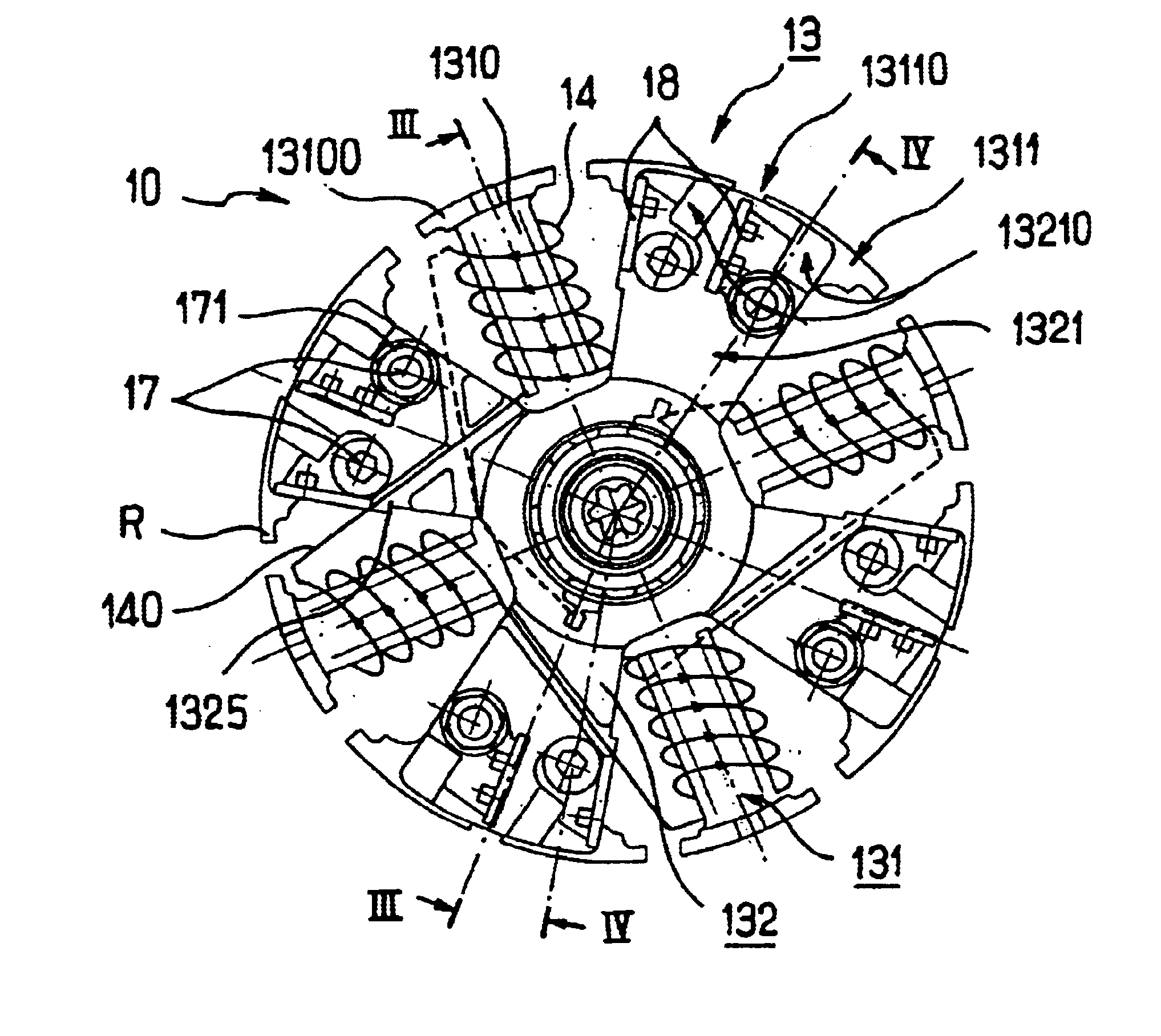
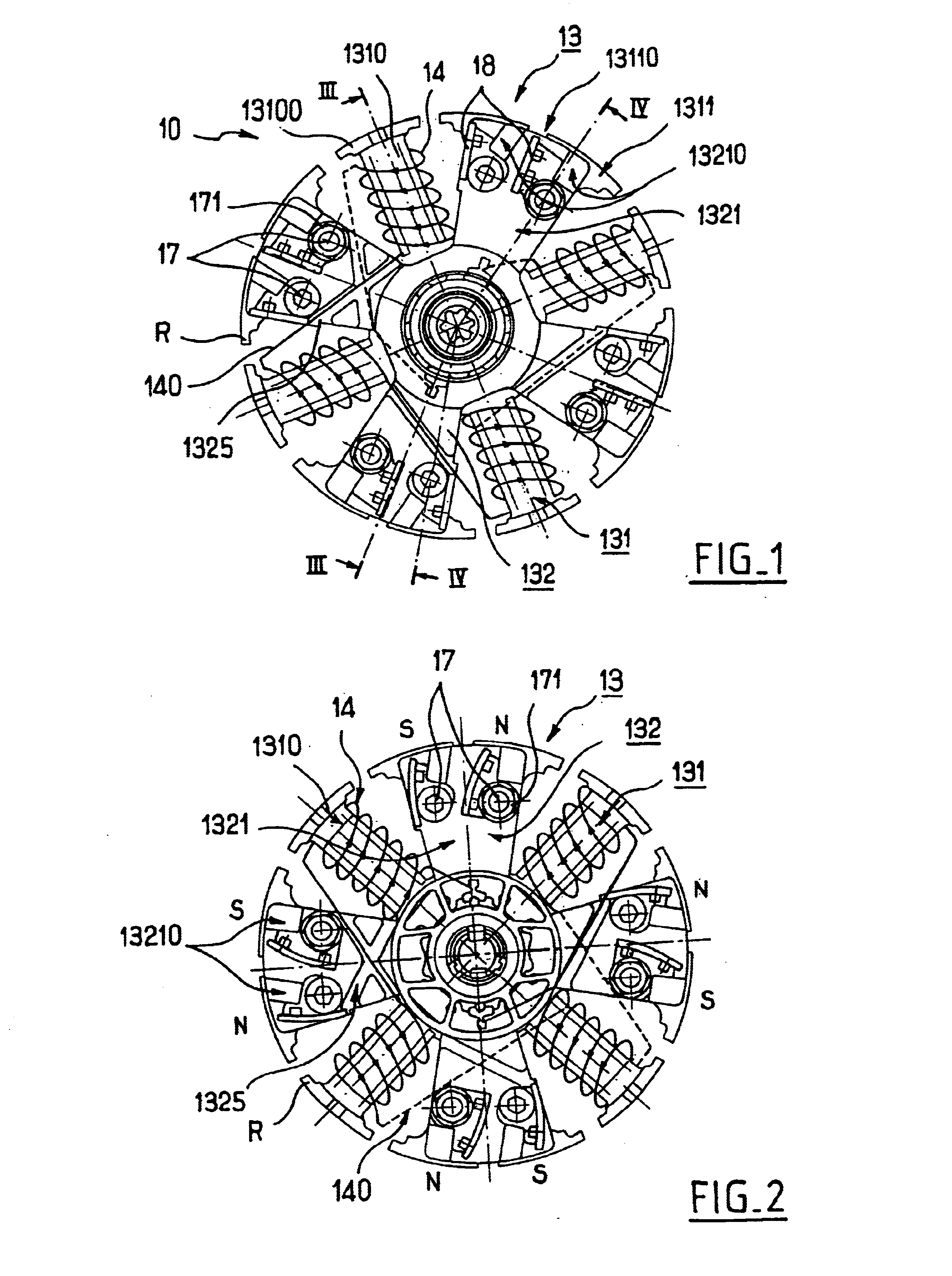
By reference first of all to FIG. 1, the rotor of a rotating machine, such as an alternator or an alternator / starter, has been represented overall by the reference 10. This machine is preferably intended to be employed in a motor vehicle.

As a reminder, it will be recalled that an alternator / starter is a rotating electric machine able to work in reversible fashion, on the one hand, as an electricity generator--alternator function and, on the other hand, as an electric motor especially for starting the internal-combustion engine of the motor vehicle. Such an alternator / starter is described, for example, in the document WO 01 / 69762, to which reference should be made for further details.

In the side view of FIG. 1, which reveals an axial extremity of the rotor, the cut-out contour of the rotor is seen clearly.

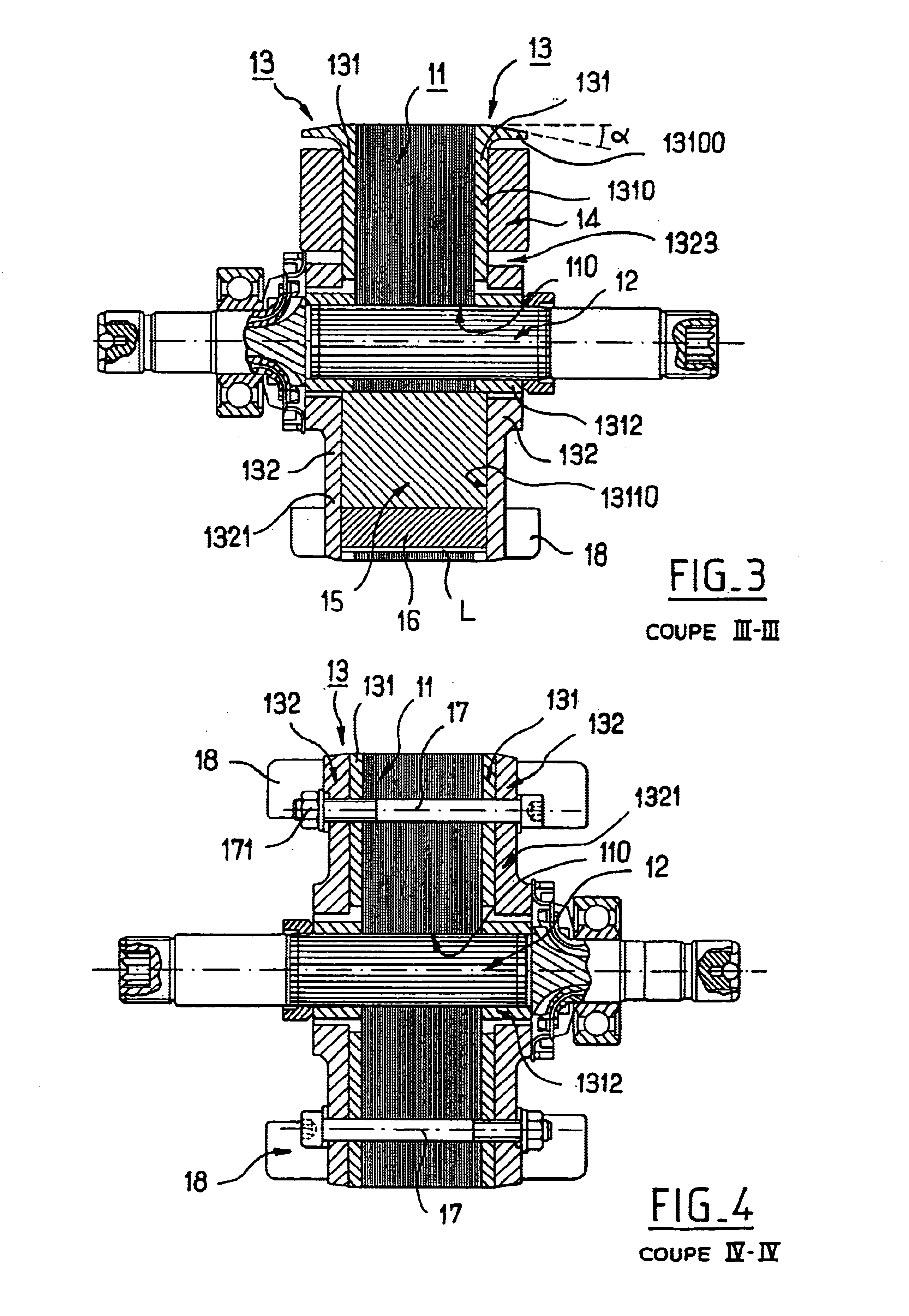
As is apparent in FIGS. 3 and 4, the structure of this rotor includes an assembly of magnetically conducting metal plates 11, all the plates 11 having the same contour. These plates...


PUM


Abstract

The invention relates to a rotating electric machine, especially an alternator or alternator / starter for motor vehicles, including a stator surrounding a rotor (10) equipped with a pack of metal plates, a gap between the stator and the rotor, permanent magnets integrated into the rotor and excitation coils (14) integrated into the rotor, in which the excitation coils are wound around salient poles (1310) cut out in the pack of metal plates of the rotor, and the permanent magnets are accommodated in housings (13110) formed in the pack of plates of the rotor and open towards the periphery of the rotor, characterized in that the housings (13110) are closed axially at each of their ends by a non-magnetic retaining piece (13) equipped with a part intended to come into abutment with the magnets, and in that the retaining piece features recesses for accommodations [sic] of the buns of the excitation coils (14).

Description

The present invention relates in a general way to rotating electric machines.More precisely, the invention relates to rotating machines of the alternator or alternator / starter type, which are employed in motor vehicles.And yet more precisely, the invention relates to the rotating machines the rotor of which comprises permanent magnets as well as one or more excitation coils.Such rotating machines are said to have compound excitation; the excitation of the coil or coils placed in the rotor, driven by a suitable electrical power supply, makes it possible to strengthen or reduce the power delivered by the machine (the sign of the electrical power supply delivered to the excitation coils possibly being reversed).These compound-excitation machines thus make it possible to enhance the effectiveness of the machine and its flexibility of use.STATE OF THE ARTAn example of such a machine is disclosed by the document EP 741 444. The rotor more particularly set out in FIG. 5 of this document ha...

Claims


Application Information

Patent Timeline
Patent Type & Authority Patents(United States)
IPC IPC(8): H02K1/22H02K21/04H02K21/00H02K9/04H02K1/24H02K3/24H02K3/52H02K19/22
CPCH02K11/048H02K21/042H02K9/04H02K3/527H02K9/06H02K2203/06H02K11/05H02K1/27
Inventor AKEMAKOU, ANTOINE DOKOU
Owner VALEO EQUIP ELECTRIC MOTEUR
Learn More