Beamformer for multi-beam receive antenna

a beamformer and antenna technology, applied in the direction of individual energised antenna arrays, direction finders using radio waves, instruments, etc., can solve the problems of prohibitively expensive approaches, large size, and complex systems, and achieve low computational overhead, high data rate, and the effect of replacing the multiplicity of antenna hardwar

Inactive Publication Date: 2004-08-31
EMS TECHNOLOGIES
View PDF19 Cites 67 Cited by
  • Summary
  • Abstract
  • Description
  • Claims
  • Application Information

AI Technical Summary

Benefits of technology

Advantageously, the present invention may be used to create a multi-beam phased array antenna system using a single programmable phase and gain control device for each antenna element, a single beam forming combiner for the array, and a single beam decoder or filter for the array. That is, the invention allows a beam encoder implemented through software running on a beam forming computer, and a cooperating beam decoder, such as a conventional CDMA or Doppler filter, to effectively replace the multiplicity of antenna hardware found in conventional multi-beam phased array antenna systems. In addition, a conventional single-beam phased array antenna system may already include at least one programmable phase and gain control device for each antenna element, at least one beam forming combiner, at least one beam forming computer, and at least one Doppler filter. For this reason, the present invention may be used to upgrade many conventional single-beam ph...

Problems solved by technology

This conventional approach requires 100,000 phase and gain devices and 100 beam forming combiners, which typically results in a system that is exorbitantly expensive, complex to construct, large in size, and heavy.
Any one or more of these penalties may be critical for a particular application.
This option, of course, limits the flexibility of t...

Method used


Image

  • Beamformer for multi-beam receive antenna
  • Beamformer for multi-beam receive antenna
  • Beamformer for multi-beam receive antenna

Examples


Embodiment Construction

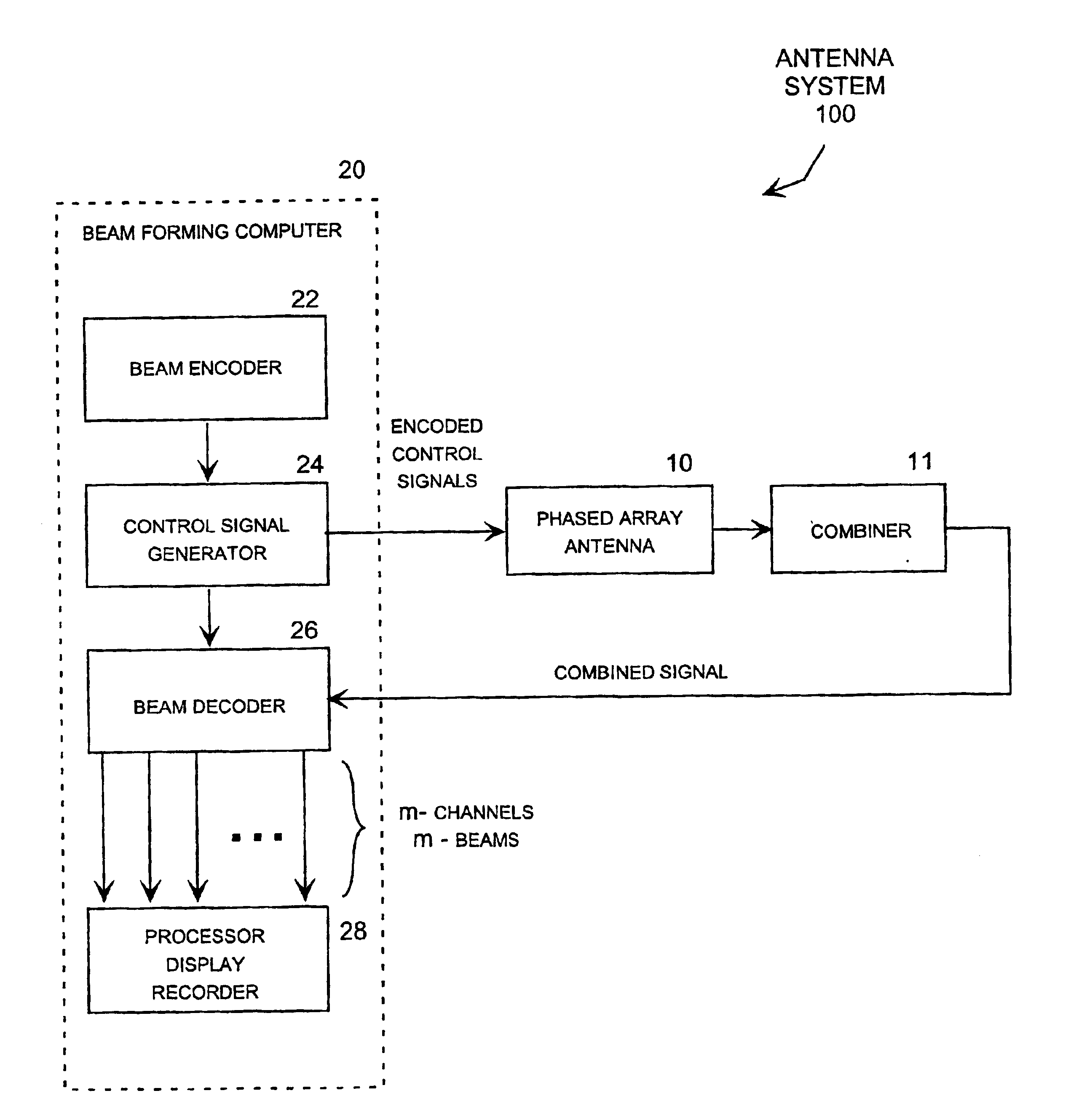
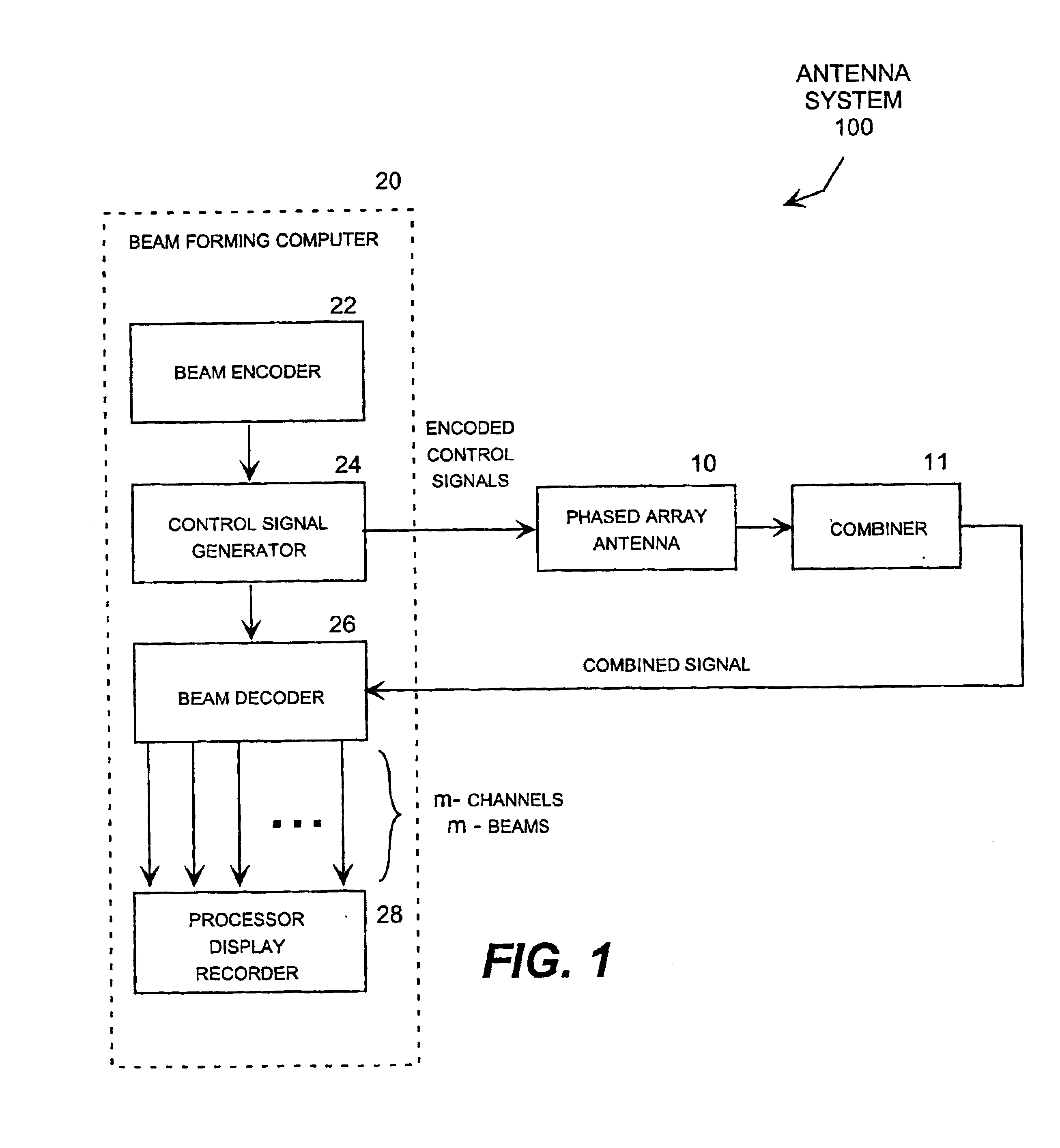
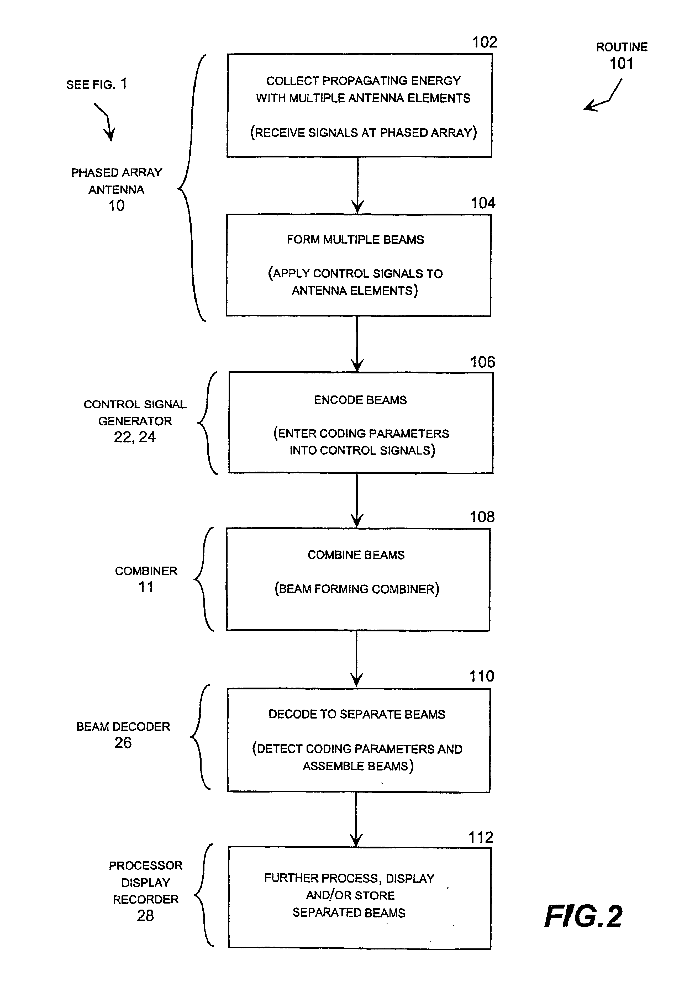
Briefly described, the invention may be embodied in a phased array antenna system that is operative to simultaneously form multiple beams without requiring an undue amount of hardware. The phased array antenna system collects propagating energy in a number of antenna elements to form multiple beams, encodes the beams as the energy is collected, combines the encoded beams, and then decodes the combined signal to separate the beams. In this way, the beams can be formed with a single set of antenna hardware instead of requiring a multiplicity of antenna hardware, one for each beam, as is needed in prior art multi-beam antenna systems. This greatly reduces the cost, complexity, size and weight of the antenna system.

Preferably, the beams are encoded on separate orthogonal code channels corresponding to conventional CDMA filter channels or frequency code channels corresponding to conventional Doppler filter channels, although other coding techniques can be employed. In the instance of cod...


PUM


Abstract

A phased array antenna system that is operative to simultaneously form multiple beams without requiring an undue amount of hardware. The system collects propagating energy with a number of antenna elements to form multiple beams, encodes the beams as the energy is collected, combines the encoded beams, and then decodes the combined signal to separate the beams. In this way, the beams can be formed with a single set of antenna hardware instead of requiring a multiplicity of antenna hardware, one for each beam. Frequency coding may be implemented by repeatedly applying a Doppler phase shift to each beam, and then using a Doppler filter to separate the beams. Alternatively, a code division multiplexing technique may be implemented by using a CDMA code generator to apply a code to each beam, and then using a CDMA filter to separate the beams.

Description

TECHNICAL FIELDThe present invention relates to phased array antenna systems, such as radar, and more particularly relates to a beam former that generates encoded control signals that drive the antenna elements of a phased array to receive multiple beams while allowing a filter to detect coding parameters contained in the control signals to separate the multiple beams from a combined signal received from the antenna.BACKGROUND OF THE INVENTIONPhased array antenna systems, such as those used for radar systems, take advantage of the phase differential that occurs according to the direction of coherent propagating energy. For example, in a simple array of two closely spaced antenna elements lying in a plane and both facing forward, an incoming signal coming straight from the forward direction would be received at the same time at both elements, resulting in signals at each element having the same phase, which are referred to as "in-phase." But if the energy approaches the elements at a...

Claims


Application Information

Patent Timeline
IPC IPC(8): H01Q25/00H04B7/08H01Q3/26H01Q21/06
CPCH01Q3/26H01Q21/061H01Q25/00H04B7/0837
Inventor HOWELL, JAMES M.
Owner EMS TECHNOLOGIES
Why Eureka
Try Eureka