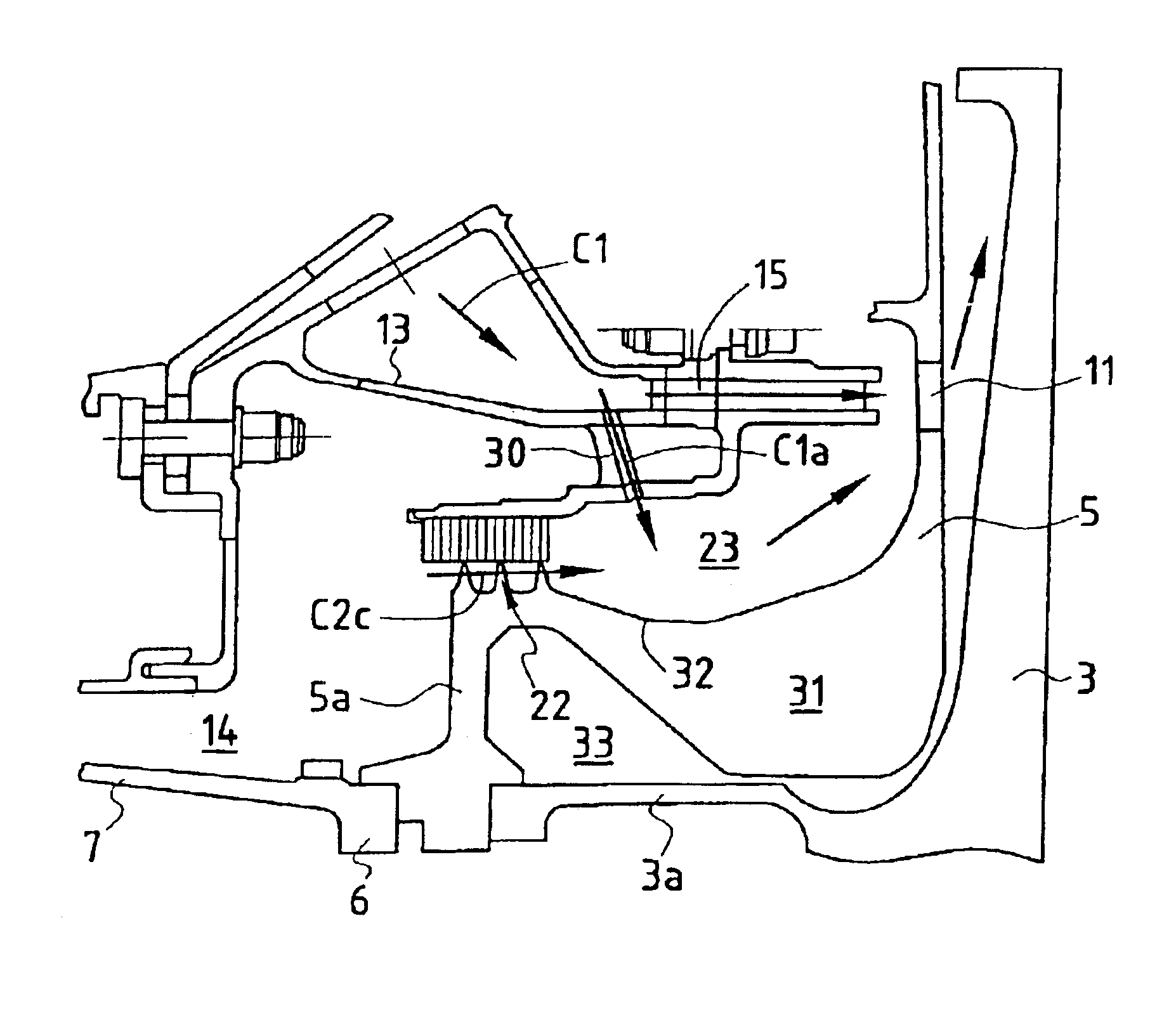
Cooling the upstream end plate of a high pressure turbine by means of a system of dual injectors at the end of the combustion chamber

a technology of high-pressure turbines and injectors, which is applied in the direction of piston pumps, vessel construction, marine propulsion, etc., can solve the problems of reducing the performance of the turbine, increasing the flow rate, and increasing the temperature of the upstream face of the end plate downstream from the second baffle, so as to and improve the efficiency of the turbine. , the effect of improving the li

Inactive Publication Date: 2004-09-07
SN DETUDE & DE CONSTR DE MOTEURS DAVIATION S N E C M A
View PDF11 Cites 23 Cited by
  • Summary
  • Abstract
  • Description
  • Claims
  • Application Information

AI Technical Summary

Benefits of technology

The object of the invention is to lower the temperature of the upstream face of the end plate in order to make it easier to dimension for overspeed, to increase its lifetime, and to be able to use a low cost material.
This third air flow that is pre-entrained and injected downstream from the baffle under the main injectors thus serves to reduce the relative total temperature of the air cooling the upstream face of the end plate downstream from the second baffle. This third flow of air mixes with the leakage flow from the baffle under the injectors and is exhausted downstream from the main injectors of the turbine into the circuit for feeding the high pressure turbine wheels.

Problems solved by technology

This increase in flow rate increases the temperature of the cooling air for the blades because heated air is dumped into the blade cooling circuit, and reduces the performance of the turbine because of the air dumped into the turbine stream.
The temperature of the upstream face of the end plate downstream from the second baffle is thus quite high and is poorly controlled.

Method used


Image

  • Cooling the upstream end plate of a high pressure turbine by means of a system of dual injectors at the end of the combustion chamber
  • Cooling the upstream end plate of a high pressure turbine by means of a system of dual injectors at the end of the combustion chamber
  • Cooling the upstream end plate of a high pressure turbine by means of a system of dual injectors at the end of the combustion chamber

Examples


Embodiment Construction

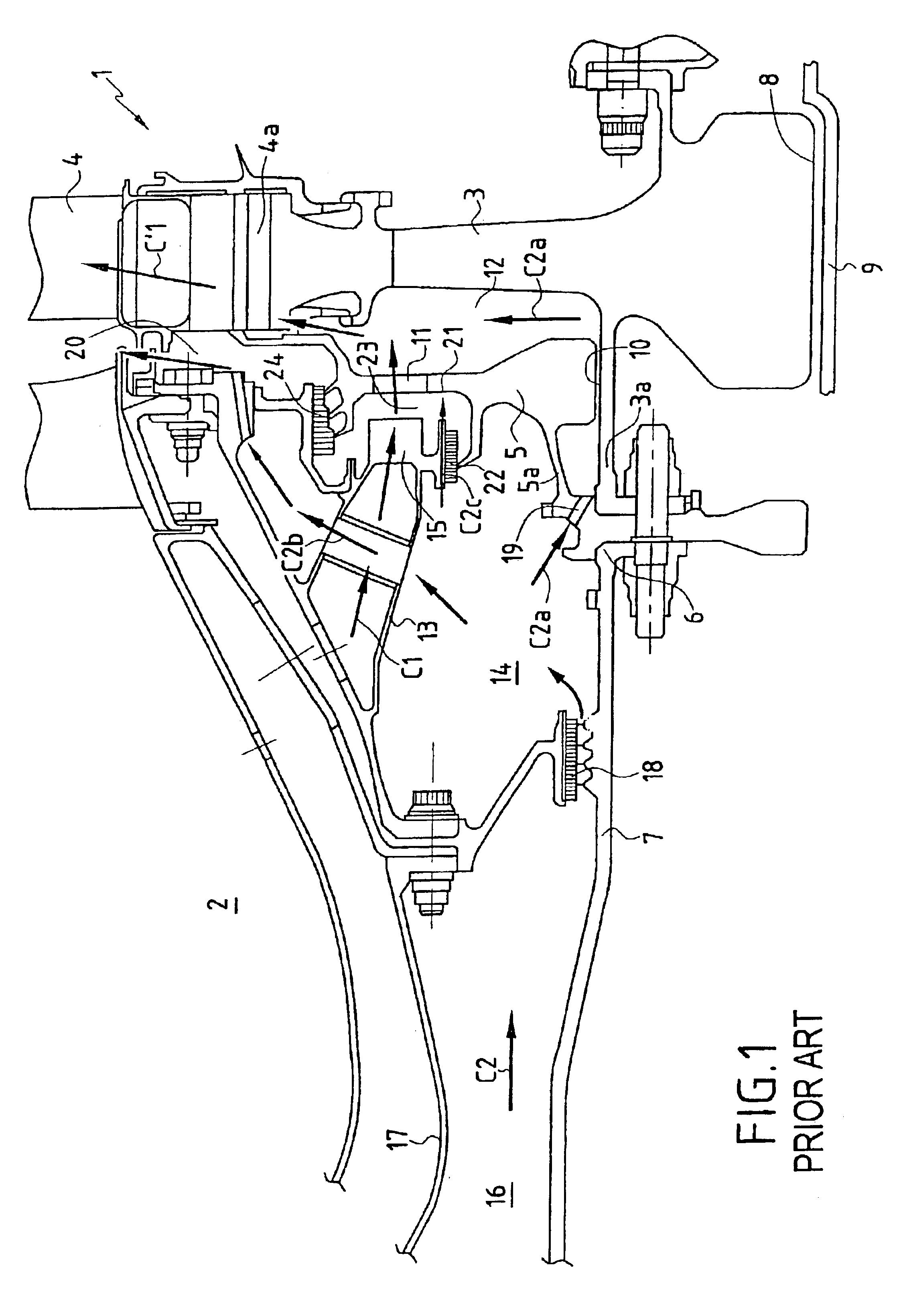
The state of the art shown in FIG. 1 is described in the introduction and needs no further explanation.

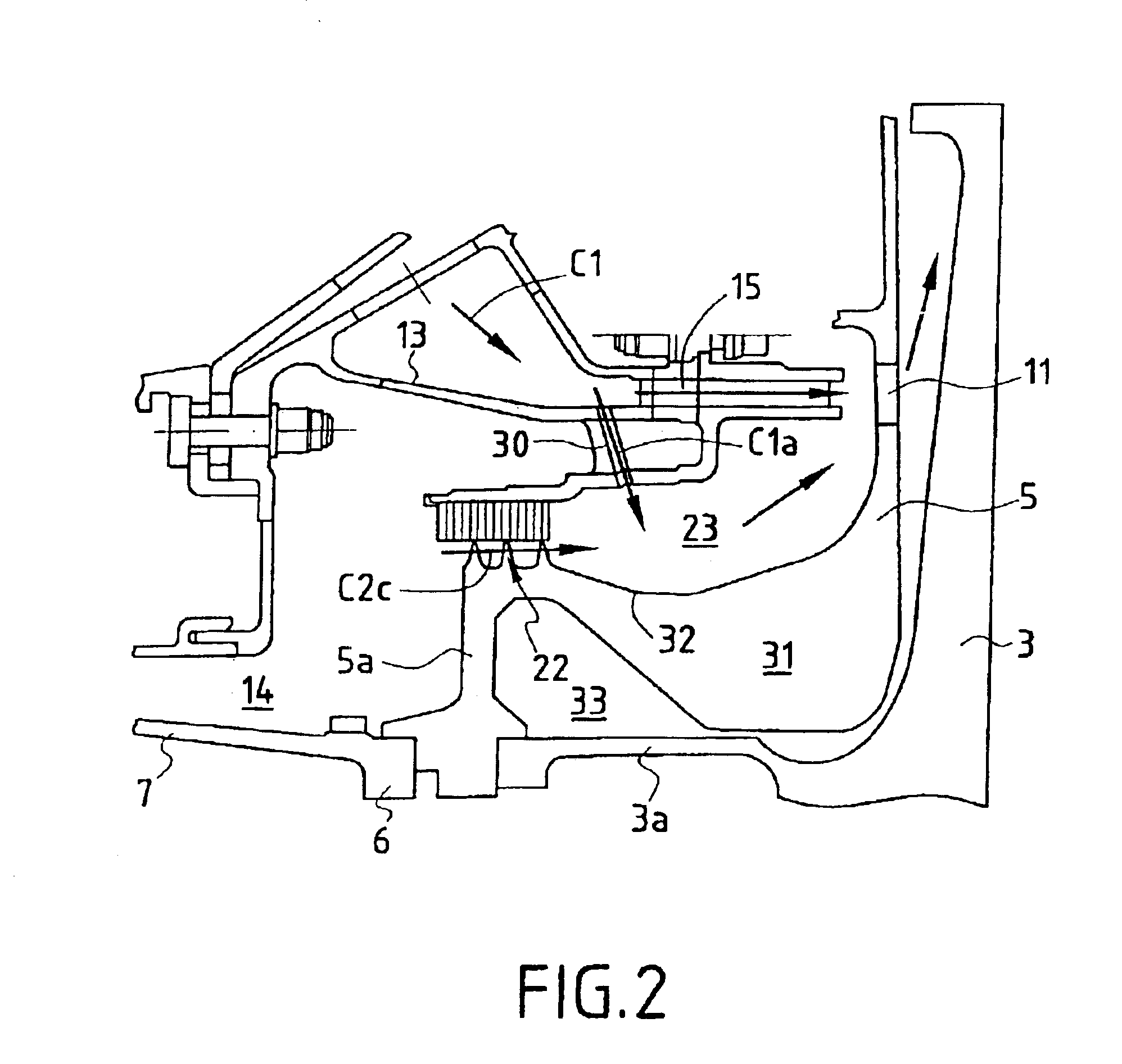
FIG. 2 shows a turbine rotor 1 which differs from that shown in FIG. 1 by the fact that the enclosure 23 situated downstream from the second baffle 22 is fed with air firstly by an air leak C2c coming from the enclosure 14 via the second baffle 22, and secondly by an air flow C1a delivered by a branch connection formed between the duct 13 delivering the first air flow C1 and the enclosure 23. The branch connection is constituted by a plurality of bores 30 opening out at one end into the inlets of the main injectors 15, and at the other end into the enclosure 23 immediately downstream from the second baffle 22. The bores 30 are cylindrical and inclined tangentially in the direction of rotation of the turbine rotor 1.

As can be seen in FIG. 2, the radially inner portion 31 of the end plate 5 is bulky in shape, and it extends axially towards the front end of the engine to the radial fl...


PUM


Abstract

The invention relates to a device for ventilating a high pressure turbine rotor which comprises a turbine disk and an upstream end plate. A first circuit for cooling blades delivers a first air flow via main injectors and holes formed in the end plate. A second cooling circuit delivers a second air flow through a discharge baffle situated downstream from the compressor, a fraction of this second flow serving to cool the upstream top face of the end plate through a second baffle situated beneath the main injectors. A branch connection is provided between the first circuit and the enclosure situated downstream from the second baffle and it delivers a third flow which is set into pre-rotation by additional injector means formed in the form of inclined bores.

Description

The invention relates to the field of ventilating high pressure turbine rotors in turbojets.More precisely, the invention relates to a ventilation device for a high pressure turbine rotor of a turbomachine, said turbine being disposed downstream from the combustion chamber and comprising firstly a turbine disk presenting an internal aperture and an upstream flange for fixing to the downstream cone of a high pressure compressor, and secondly an end plate disposed upstream from said disk and separated therefrom by a cavity, said end plate comprising a solid radially inner portion likewise having an internal aperture, through which the upstream flange of said disk extends, and an upstream flange for being fixed to said downstream cone, said device comprising a first circuit for cooling blades fed with a first flow of air taken from the end of the combustion chamber and delivering said first flow of air into said cavity via main injectors disposed upstream from said end plate, and venti...

Claims


Application Information

Patent Timeline
Patent Type & Authority Patents(United States)
IPC IPC(8): F01D11/00F01D5/00F01D5/02F01D5/30F01D11/02F01D5/08F01D25/00F02C7/18
CPCF01D5/081F01D5/3015F01D11/02
Inventor COULON, SYLVIESTANGALINI, GERARDTAILLANT, JEAN-CLAUDEADAM, GERARD
Owner SN DETUDE & DE CONSTR DE MOTEURS DAVIATION S N E C M A
Why Eureka
Try Eureka