Method for operating a turbine

a turbine and turbine blade technology, applied in the ignition of the turbine/propulsion engine, the engine starter, the machine/engine, etc., can solve the problems of unusual mechanical stress in the blades, quick speed, windage effects, etc., to prevent windage effects and astatic behaviour with respect to speed

Inactive Publication Date: 2004-09-21
GENERAL ELECTRIC TECH GMBH
View PDF11 Cites 10 Cited by
  • Summary
  • Abstract
  • Description
  • Claims
  • Application Information

AI Technical Summary

Benefits of technology

It is a particular object of the invention to provide a method that is unambiguous in the choice of variables for speed control. It is a further particular object of the invention to provide a turbine speed control by which windage effects and astatic behaviour with respect to speed are prevented in an air expansion turbine.

Problems solved by technology

A specific problem encountered during start-up of the turbine of this type is that the turbine, that is accelerated by means of a relatively small air mass flow, can quickly reach speeds at which windage effects due to insufficient flow volume can occur in the final stages of the gas turbine.
Windage is caused by a faulty air flow about the blades, which causes unusual mechanical stress in the blades.
Furthermore, this type of turbine tends to develop an "astatic" behavior with respect to speed, which is essentially due to the lack of a counter torque.
If during a start-up, the speed is chosen as a control variable and the brake torque is very small, then uncontrolled windage can easily occur.

Method used


Image

  • Method for operating a turbine
  • Method for operating a turbine
  • Method for operating a turbine

Examples


Embodiment Construction

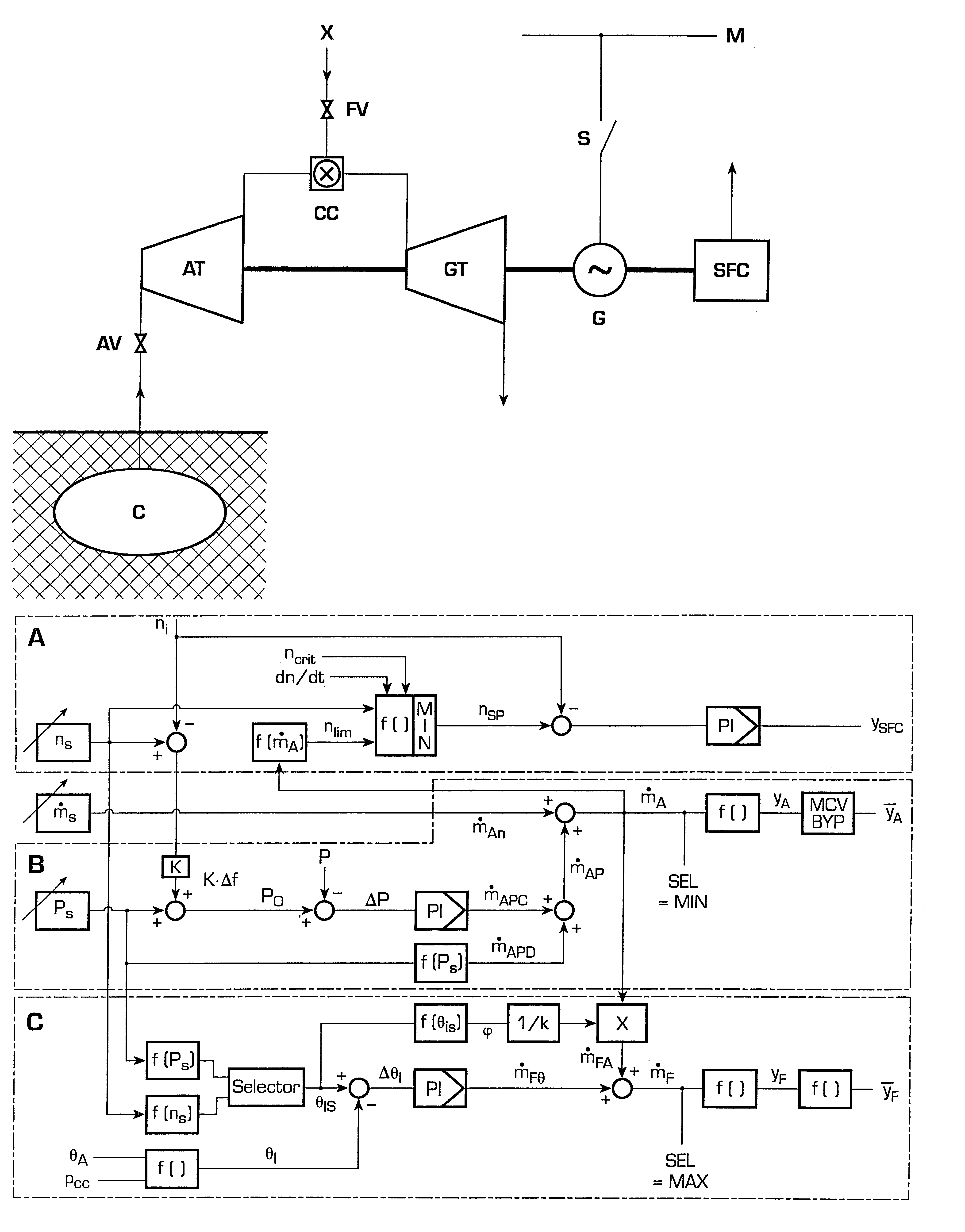
The method of operation according to the invention depends on the turbine speed that it is applied to. The aforementioned lower turbine speed range comprises the speeds up to approximately 40% of the full operating speed and is the speed range where the SFC cannot be put into operation for electrical reasons (generator excitation). This may be the case, for example, during purging. Within this range of turbine rotor speeds, the air mass flow as set by the air inlet valves is set by open loop control according to a prescribed purging rule and the resulting turbine speed is left free to develop. In this speed range, there is typically also no potential windage effects.

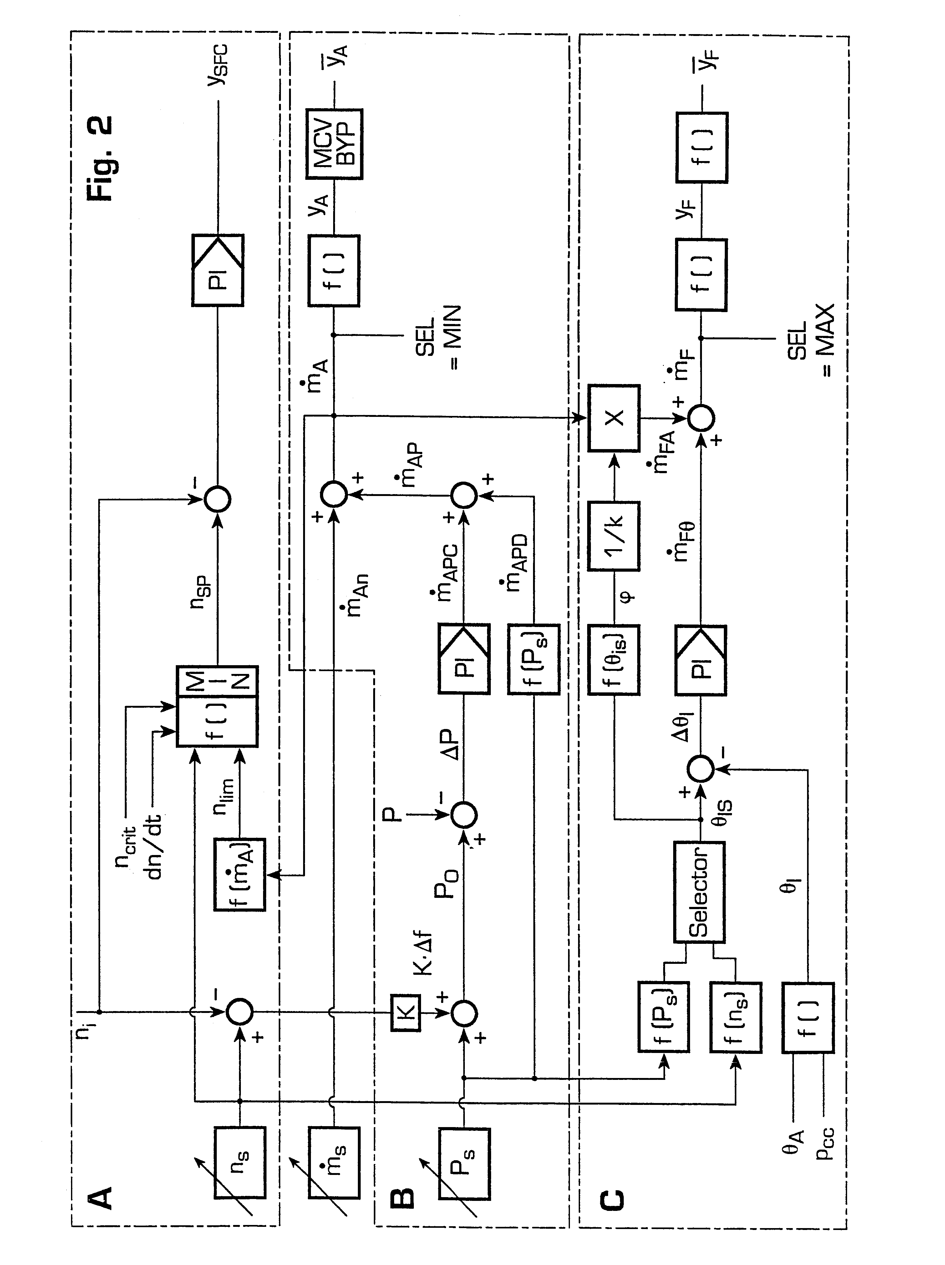
The aforementioned higher speed range includes the speeds above the approximately 40% of the full operating speed and is that speed range within which the SFC can be activated. In this higher speed range the air mass flow is controlled according to the circuitry shown in FIG. 2.

FIG. 2 shows schematically the speed contro...


PUM


Abstract

A method of operating a turbine arranged in a compressed air energy storage power generation plant comprises an open-loop control of an air mass flow applied within a lower turbine speed range and a closed-loop control of the turbine speed within a higher turbine speed range. The open-loop control comprises the control of the air mass flow by means of air inlet valves and a free development of the turbine speed. The closed-loop control comprises the control of the turbine speed by means of a speed controller, which is acted upon by a speed limiting value determined according to the current air mass flow and a windage calculation. The speed controller activates a static frequency converter in the case that the turbine speed reaches values that are critical with respect to turbine windage or rotor dynamics.

Description

The invention pertains to a method of operating a turbine arranged in a compressed air energy storage (CAES) power generation plant and in particular to a method for a controlled start-up and shut-down of such a turbine.A typical compressed air energy storage (CAES) power generation plant as shown in FIG. 1 comprises a cavern (C) for compressed air, which is used to drive a single-shaft expansion turbine consisting of an air expansion turbine (AT) followed by a combustion chamber (CC). It furthermore comprises a gas turbine (GT), which during normal operation drives a fixedly coupled generator (G) in synchronisation with the mains.Speed and power control of the turbine is usually realised by a coordinated control of valves, in particular of the air inlet valves (AV) at the air turbine inlet as well as the fuel inlet valves (FV) at the combustion chamber. The following disclosure pertains to a CAES power generation plant as shown in the schematic of FIG. 1 as well as variants thereof...

Claims


Application Information

Patent Timeline
Patent Type & Authority Patents(United States)
IPC IPC(8): F01D19/00F01D21/00F02C6/16F02C7/26F02C9/00F02C6/00F02C9/16F02C7/057
CPCF01D19/00F01D21/00F02C6/16F02C7/26F02C9/16Y02E60/15F05D2270/021Y02E60/16
Inventor MATHIAS, GERNOTSEKETA, BOZIDAR
Owner GENERAL ELECTRIC TECH GMBH
Why Eureka
Try Eureka