
Method and apparatus for providing integrated broadband polarization control

Inactive Publication Date: 2004-09-28
WSOU INVESTMENTS LLC +1
View PDF4 Cites 3 Cited by
  • Summary
  • Abstract
  • Description
  • Claims
  • Application Information

AI Technical Summary

Benefits of technology

The invention comprises a method and apparatus for providing integrated broadband polarization control. The invention enables an integrated polarization controller, suitable for realization on low-cost material in planar waveguide technology, and compact in size, which can transform a SOP to another arbitrary SOP for a wide range of wavelengths for use in optical communication systems, such as those utilizing wavelength division multiplexing (WDM).

Problems solved by technology

As light propagates through an optical fiber, variables such as temperature and stress can cause random and arbitrary changes in the state of the light's polarization, reducing the distance that the light travels due to signal degradation.
These changes in the state of polarization can cause problems in fiber optic applications such as optical communication systems and sensors.
This hybrid combination however, can be costly and physically occupies a large form factor.

Method used


Image

  • Method and apparatus for providing integrated broadband polarization control
  • Method and apparatus for providing integrated broadband polarization control
  • Method and apparatus for providing integrated broadband polarization control

Examples


Embodiment Construction

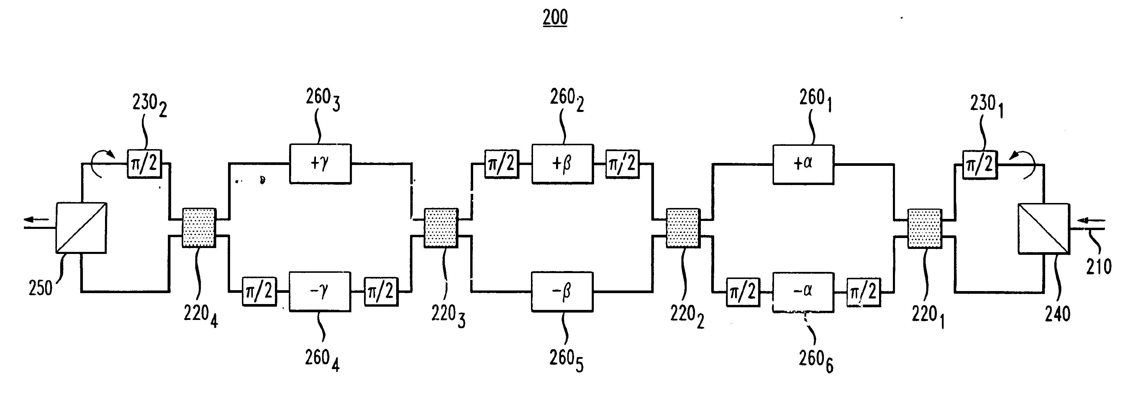
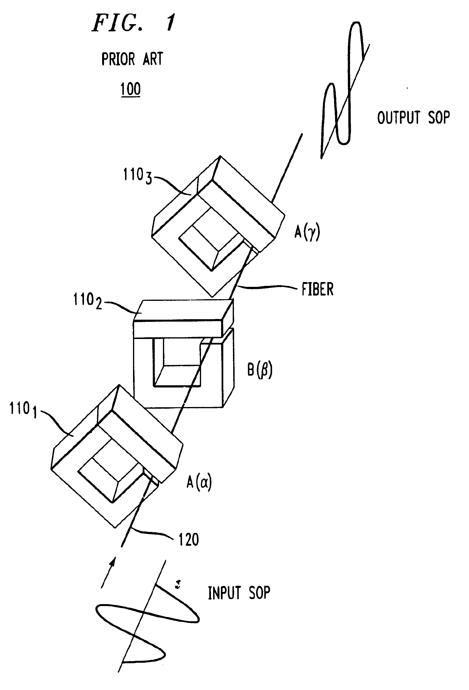
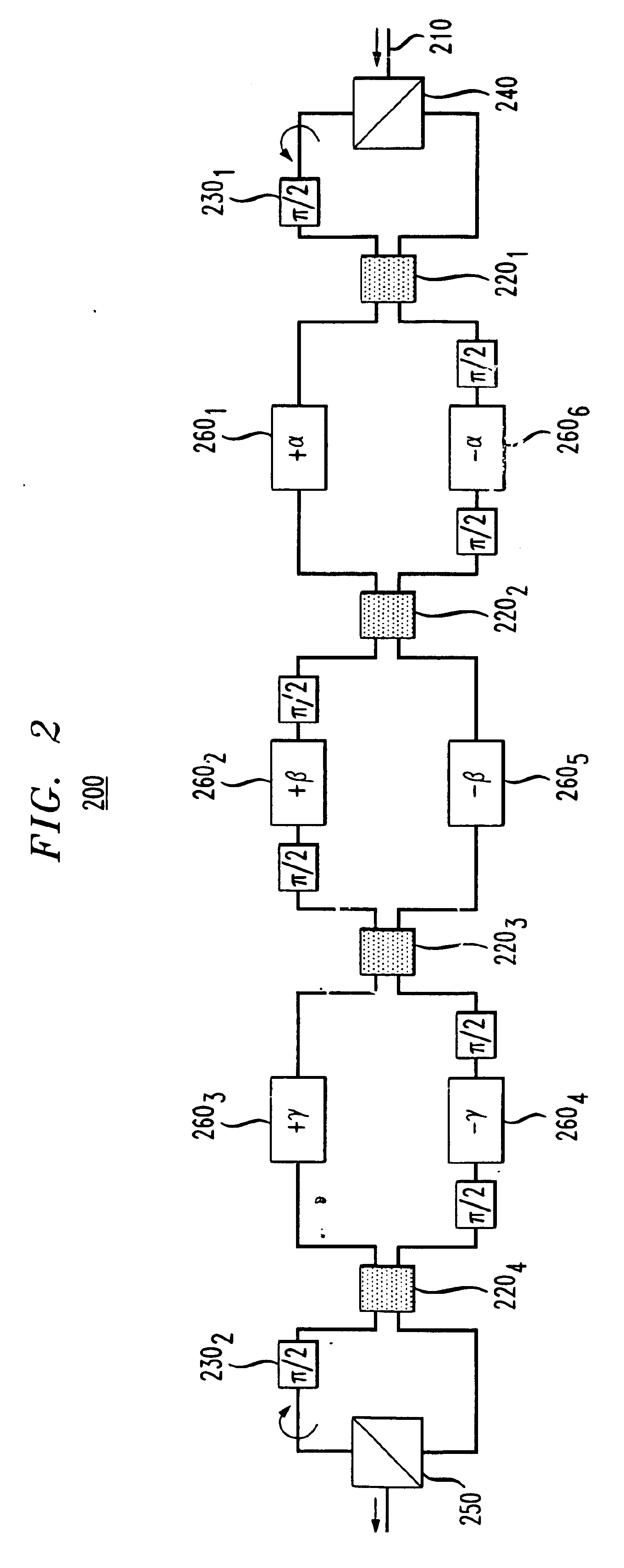
FIG. 1 depicts an embodiment of a single channel polarization controller design. (See R. Noe, H. Heidrich, D. Hoffman, "Endless Polarization Control Systems for Coherent Optics," Journal of Lightwave Technology, pp. 1199-1207, 1988). The polarization controller 100 of FIG. 1 provides polarization tuning of an input optical signal's state of polarization (SOP) to a desired output SOP. Briefly stated, an optical signal propagates through the waveguide 120 and subsequently reaches the polarization controller 100. The polarization controller of FIG. 1 includes three fiber squeezers 110.sub.1, 110.sub.2, 110.sub.3. The SOP of the input optical signal is then manipulated to a desired SOP due to the squeezing influence that the fiber squeezers 110.sub.1, 110.sub.2, 110.sub.3 have on the fiber birefringence. Unfortunately, fiber squeezers, as depicted in FIG. 1, occupy a large form factor and cannot be designed in silicon optical bench technology. Thus there exists a need to emulate the pol...


PUM


Abstract

An integrated broadband polarization controller is based on planar waveguide technology. The integrated broadband polarization controller emulates the polarization control function of an existing single channel polarization controller in a device that can be built in planar waveguide technology, and is expanded from single channel operation to broadband channel operation by designing the control degrees of freedom to be wavelength selectively addressable.

Description

FIELD OF THE INVENTIONThis invention relates to the field of optoelectronics and, more specifically, to polarization controllers.BACKGROUND OF THE INVENTIONLight is an electromagnetic wave composed of electric and magnetic fields. The orientation of these fields defines the light's polarization. As light propagates through an optical fiber, variables such as temperature and stress can cause random and arbitrary changes in the state of the light's polarization, reducing the distance that the light travels due to signal degradation. These changes in the state of polarization can cause problems in fiber optic applications such as optical communication systems and sensors. Polarization controllers can reduce signal degradation in optical systems by converting any incoming polarization state back to the intended polarization state during optical transmissions. The principle of the polarization controller is that a desired polarization state is obtained by using appropriate phase retarder...

Claims


Application Information

Patent Timeline
IPC IPC(8): G02F1/01G02B27/28G02B6/34
CPCG02B6/12007G02B6/12021G02B27/286G02F1/0136G02B6/272G02B6/2766G02B6/2773
Inventor MOELLER, LOTHAR BENEDICT
Owner WSOU INVESTMENTS LLC
Learn More