Wind power system

a wind power system and wind turbine technology, applied in the direction of electric generator control, machines/engines, final product manufacturing, etc., can solve the problems of undesirable noise generated by traditional turbine blade assemblies, the cost of on-site wind power generation typically exceeds the cost of power derived from the most common traditional power generation sources, and the general application of small-scale wind power. achieve the effect of efficient cooling of the generator, simple erection and installation

Inactive Publication Date: 2004-10-05
BARTLETT LEXINGTON
View PDF11 Cites 88 Cited by
  • Summary
  • Abstract
  • Description
  • Claims
  • Application Information

AI Technical Summary

Benefits of technology

It is a further object and feature of the present invention to provide such a system that has a lower cost to produce and operate than other alternate power generation systems. It is a further object and feature of the present invention to provide such a system that has high power generation efficiency.
It is a further object and feature of the present invention to provide such a system that is relatively easy to install and maintain.
It is a further object and feature of the present invention to provide such a system that can operate in low wind speed conditions.
It is a further object and feature of the present invention to provide such a system that allows relatively versatile and simple erection and installation.
It is a further object and feature of the present invention to provide such a system that efficiently cools the generator.

Problems solved by technology

Typically, the principal limiting factor in the general application of small-scale wind generation is cost.
Today, the cost of on-site wind power generation typically exceeds the cost of power derived from the most common traditional power generation sources, i.e., utility-scale power grids.
Other limiting factors include undesirable noise generated by traditional turbine blade assemblies.
History has shown that the over-reliance on fossil fuels as the primary means of electrical power production is increasingly problematic in a volatile world energy market.
Wind turbine blades made of wood or other similarly heavy materials require relatively high initial wind speeds to start up and cannot take advantage of lower wind speeds to generate power.
Wind turbine blades made of plastic or other similarly light materials often are not stiff enough to prevent significant loss of efficiency when the shape of the blade is deformed by the wind.
Additionally, turbine blades that are not stiff enough can produce vibrations that can result in increased maintenance costs and undesirable noise.
Wind turbine blades reinforced with carbon fiber can be made stronger and lighter than traditional materials but are expensive to produce, given the cost of materials and current manufacturing methods.
In the past, the tower support structures, which elevate the turbine above the ground, have been relatively difficult to assemble / erect.
In the past, towers have been assembled by connecting segments of pipe together with threaded fittings, which are difficult to align correctly, given the typical long, unwieldy segments of pipe.
Also, the threads can become stripped in the assembly process, causing further difficulties.
Also, some towers have failed (for example, by being blown over) in high winds when the lateral supports (guy wires) have become detached at the connection to the tower mast.
In the past, these connections have failed at the welds.
The disadvantage of active cooling measures is that they tend to be expensive; whereas, the disadvantage of passive measures is that they tend to be less effective in dissipating heat quickly.

Method used


Image

  • Wind power system
  • Wind power system
  • Wind power system

Examples


Embodiment Construction

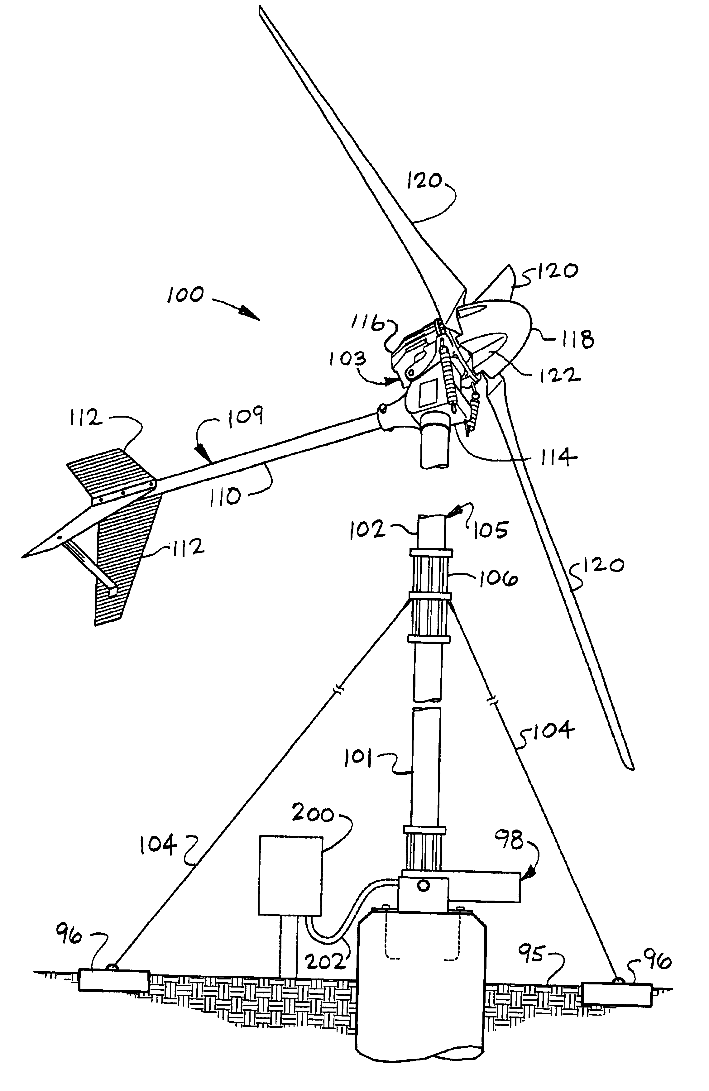
Reference is now made to the drawings. FIG. 1 is a perspective view of a wind power system 100 according to a preferred embodiment of the present invention. An overview of this wind power system 100, various specific elements of which will be further described later in this specification, will illustrate, among other things, the various components which must be structured sufficiently to overcome any excess flutter, weight, lack of stiffness, or high inertial mass of the turbine blades.

Lower pole 101 (herein embodying a first elongated member) is preferably mounted on mast base 98 (also called "base plate), which is preferably fixed in the ground 95, as shown. Compression coupler(s) 106 preferably connect lower pole 101, upper pole 102 (herein embodying a second elongated member), and guy wire(s) 104 (herein embodying at least one lateral support), as shown. To fully form support tower 105, there preferably may be additional intermediary poles between upper pole 102 and lower pole 1...


PUM

PropertyMeasurementUnit
lengthaaaaaaaaaa
angleaaaaaaaaaa
temperatureaaaaaaaaaa

Abstract

A system for the generation of electrical power using an improved 600-watt to 900-watt wind turbine system. The system comprises a wind driven generator utilizing an array of uni-directional carbon fiber turbine blades, an air-ducting nose cone, and a supporting tower structure. Additionally, a method of blade fabrication utilizing expanding foam, to achieve improved blade edge strength, is disclosed. The support tower utilizes a compressive coupler that permits standard fence pipe to be joined without welding or drilling.

Description

This invention relates to providing a system for the generation of electrical power using an improved 900-watt class wind turbine system. For centuries, man has harnessed the almost unlimited power of the wind. Today, wind-driven systems to generate electrical power range in size from large multi-megawatt utility class units to small battery charging systems used at remote monitoring stations.One class of wind turbines having a great potential for increased utilization falls in about the 600 to 900 watt range. Turbines in this power class are of suitable capacity to generate electrical power for individual residences (and similar applications having small to moderate power requirements).Typically, the principal limiting factor in the general application of small-scale wind generation is cost. Today, the cost of on-site wind power generation typically exceeds the cost of power derived from the most common traditional power generation sources, i.e., utility-scale power grids. Other li...

Claims


Application Information

Patent Timeline
Patent Type & Authority Patents(United States)
IPC IPC(8): F03D1/00F03D1/06
CPCF03D1/0675F03D1/0683Y02E10/721F05B2240/30B29C44/1228B29L2031/085Y02E10/72Y02P70/50
Inventor BARTLETT, LEXINGTON P.
Owner BARTLETT LEXINGTON
Why Eureka
Try Eureka