High peak power plasma pulsed supply with arc handling

a plasma pulsed supply and high-peak power technology, applied in the direction of vacuum evaporation coating, electrolysis components, coatings, etc., can solve the problems of not revealing any arc handling capability, commercial utilization is impractical, physical realization of a completely arc free region of operation essentially impossibl

Inactive Publication Date: 2004-10-26
ADVANCED ENERGY IND INC
View PDF4 Cites 70 Cited by
  • Summary
  • Abstract
  • Description
  • Claims
  • Application Information

AI Technical Summary

Benefits of technology

There is provided by this invention an apparatus and method for producing a high voltage pulse suited for delivering high peak power to high-density magnetron plasmas with efficient arc handling capability. A pulsing circuit comprised of an energy storage capacitor is repetitively charged and then discharged through an inductor in series with the plasma. The combination of the inductor and capacitor serve to shape the pulse, to provide an impedance match to the plasma, and to limit the current rate of rise and peak magnitude in the event of an arc. An arc is detected by either the fall of the discharge voltage below a preset voltage threshold during a pulse, or an increase in discharge current above a preset current threshold. When an arc is detected the energy storage capacitor is disconnected from the series inductor to stop the current rise. The pulsing circuit is then disconnected from the plasma load and the inductor energy is recycled to the energy storage capacitor.

Problems solved by technology

However, the technique taught by these references does not disclose any arc handling capability, and in fact suggests that an arc free region actually exists.
Unavoidable imperfections in hardware make the physical realization of a completely arc free region of operation essentially impossible, even if its existence is suggested by theory.
Use of the technique without arc handling capability makes commercial utilization impractical.
These types of arc handling methods are very costly because they may result in a complete shut down of the process wasting expensive stock material, or require dissipation of energy stored in the power supply circuits.
In high power applications short circuits to the power supply may result in extremely high currents that can cause destruction of the power supply itself, and repetitive dissipation of stored energy requires expensive resistive elements capable of high peak power and high average power, as well as the means for cooling them.

Method used


Image

  • High peak power plasma pulsed supply with arc handling
  • High peak power plasma pulsed supply with arc handling
  • High peak power plasma pulsed supply with arc handling

Examples


Embodiment Construction

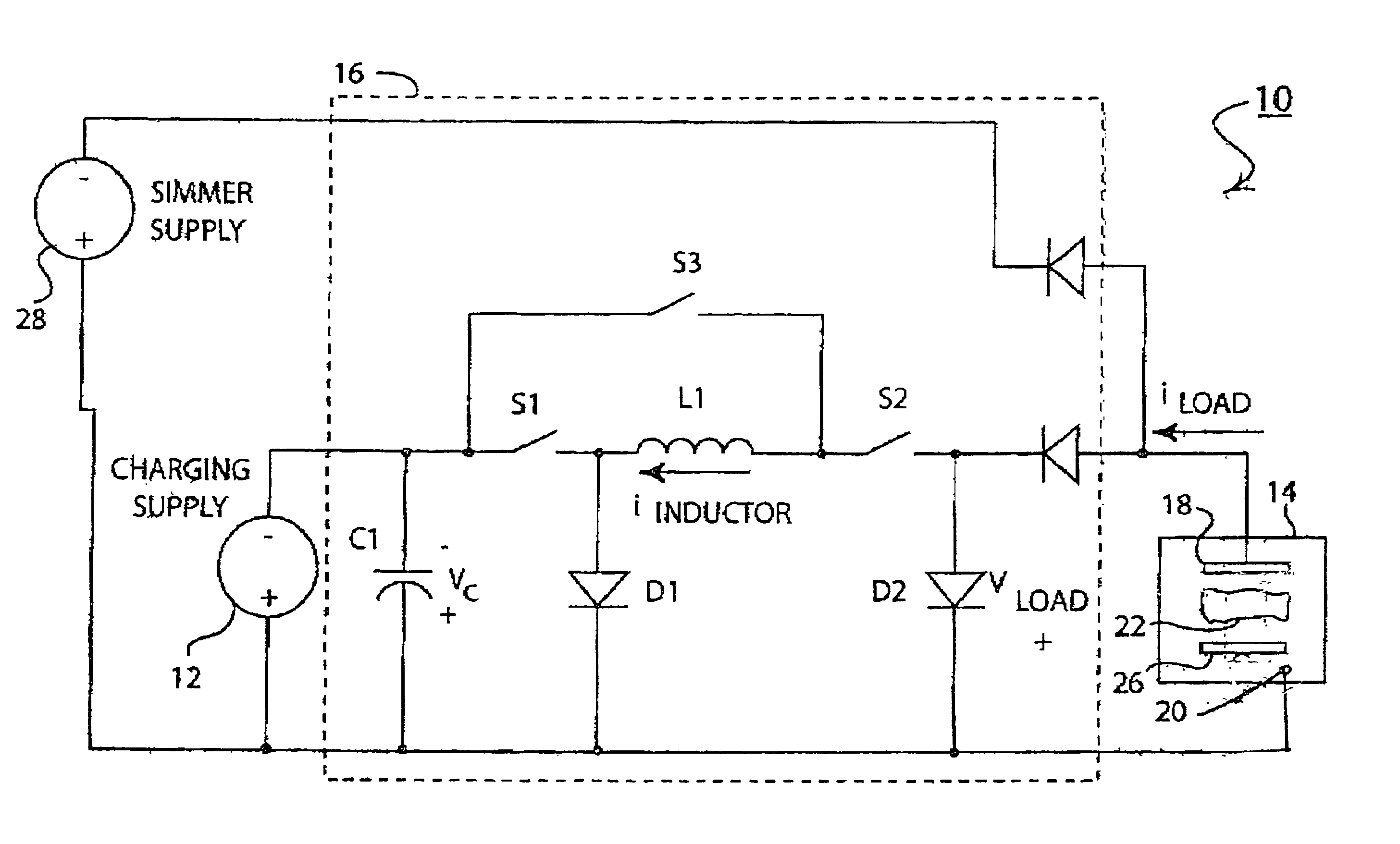
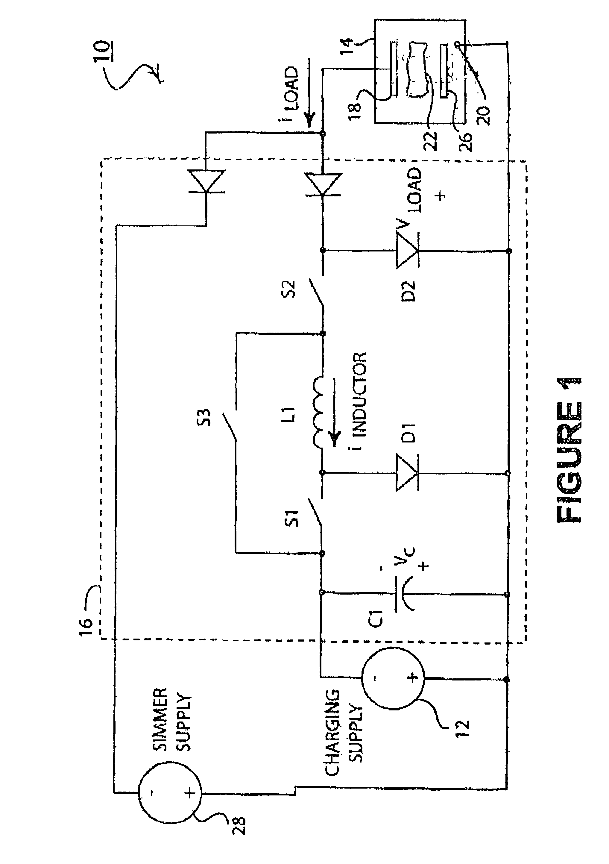
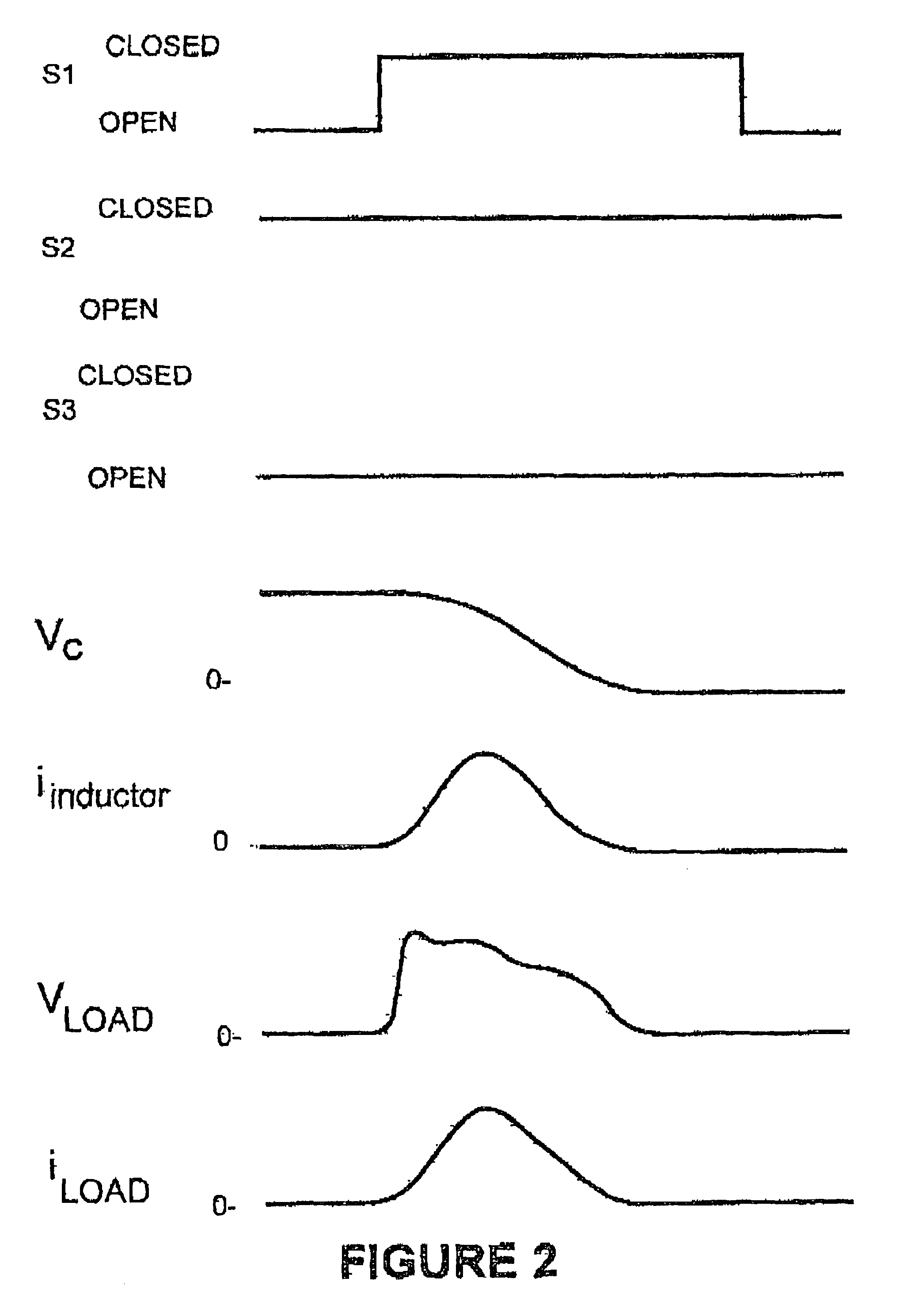
Referring to FIG. 1 there is shown a magnetron plasma processing system 10. A dc power supply 12 is connected to a magnetron plasma-processing chamber 14 via a pulsing circuit 16. The magnetron plasma-processing chamber may be a conventional magnetron chamber well known to those skilled in the art having a magnetron cathode 18 and an anode 20. The pulsed supply 16 may be of the type such as a MegaPulser.TM. model manufactured by Advanced Energy Industries, Inc. which supplies a high voltage pulse across the cathode 18 and anode 20 to ignite a plasma 22 between the electrodes in a manner well known to those skilled in the art. As with all conventional plasma processing chambers the plasma acts upon the material of the cathode 18 so as to result in a coating on a substrate 26 located within the chamber. It is generally known and well understood that at high voltages and with variances in the processing environment within the chamber, arc discharges can occur from the plasma 22 or cath...


PUM

PropertyMeasurementUnit
voltageaaaaaaaaaa
impedanceaaaaaaaaaa
current rateaaaaaaaaaa

Abstract

There is provided by this invention novel magnetron sputtering apparatus that is generally comprised of a pulsed dc power supply capable of delivering peak powers of 0.1 megaWatts to several megaWatts with a peak power density greater than 1 kW / cm2. The power supply has a pulsing circuit comprised of an energy storage capacitor and serially connected inductor with a switching means for disconnecting the pulsing circuit from the plasma and recycling the inductor energy back to the energy storage capacitor at the detection of an arc condition. The energy storage capacitor and the serially connected inductor provide an impedance match to the plasma, limits the current rate of rise and peak magnitude in the event of an arc, and shapes the voltage pulses to the plasma.

Description

1. Field of the InventionThis invention is related generally to apparatus and methods for magnetron sputtering of highly ionized, high-density metal plasmas, and more particularly to magnetron sputtering apparatus that delivers peak powers of 0.1 mega Watts to several mega Watts, with peak power density of 1 kW / cm.sup.2 and higher to a sputtering magnetron plasma load with arc handling capability.2. Brief Description of the Prior ArtIt is desirable to coat some substrates by generating metal ions and attracting the ions to the work piece by means of an electrical bias, which attracts the ions. The utility of this approach includes application of coatings to surfaces with irregularities that would prevent uniform deposition by normal sputtering, which essentially requires line of sight. Indeed coating and even filling high aspect ratio trenches in semiconductor devices is possible by biasing the wafer to attract the ions, as reported by Monteiro in JVST B 17(3), 1999 pg. 1094 and Lu ...

Claims


Application Information

Patent Timeline
Patent Type & Authority Patents(United States)
IPC IPC(8): H01J37/32H01J37/34C23CC23C14/00C23C14/35C25B9/00C25B11/00C25B13/00
CPCH01J37/34H01J37/3444H01J37/3405C23C14/35
Inventor CHRISTIE, DAVID J.
Owner ADVANCED ENERGY IND INC
Why Eureka
Try Eureka