
Response assessment

a technology of response and assessment, applied in the field of response assessment, can solve the problems of preventing high-speed measurements, affecting the measurement accuracy of fluorescent lifetime, and affecting the accuracy of response assessment,

Inactive Publication Date: 2004-11-09
UNIV OF MANCHESTER
View PDF13 Cites 10 Cited by
  • Summary
  • Abstract
  • Description
  • Claims
  • Application Information

AI Technical Summary

Benefits of technology

The present invention makes it possible to measure for example a fluorescent decay lifetime from pulse (quantum) signals resulting from only a single excitation transient of very short duration, for example a few nanoseconds, or less.
The invention is advantageous because it reduces the effect of variation of the excitation intensity.
The invention may be applied to the assessment of a large number of samples of a particular medium using a single source. Excitation may be delivered to the samples from the single source and received by a single detector. Each of the samples may receive an excitation in turn, signals from each of the samples being detected in turn, or alternatively each of the samples may receive an excitation simultaneously, with signals from all of the samples being detected in parallel. This latter approach enables rapid assessment of a large number of samples to determine whether any of them is generating a characteristic response before the application of the first approach to assess individual samples which do exhibit some characteristic response.

Problems solved by technology

These delays, coupled with the need for repeated excitation, prevent high speed measurements being obtained.
A further disadvantage of conventional fluorescence detection methods is that the intensity of successive excitation pulses may vary.
This variation of excitation pulse intensity will cause distortion of the measured fluorescent lifetime.
However, such stabilisation will not fully remove intensity variation between successive excitation pulses.
A disadvantage of normalisation is that it requires high speed electronics.

Method used


Image

  • Response assessment
  • Response assessment
  • Response assessment

Examples


Embodiment Construction

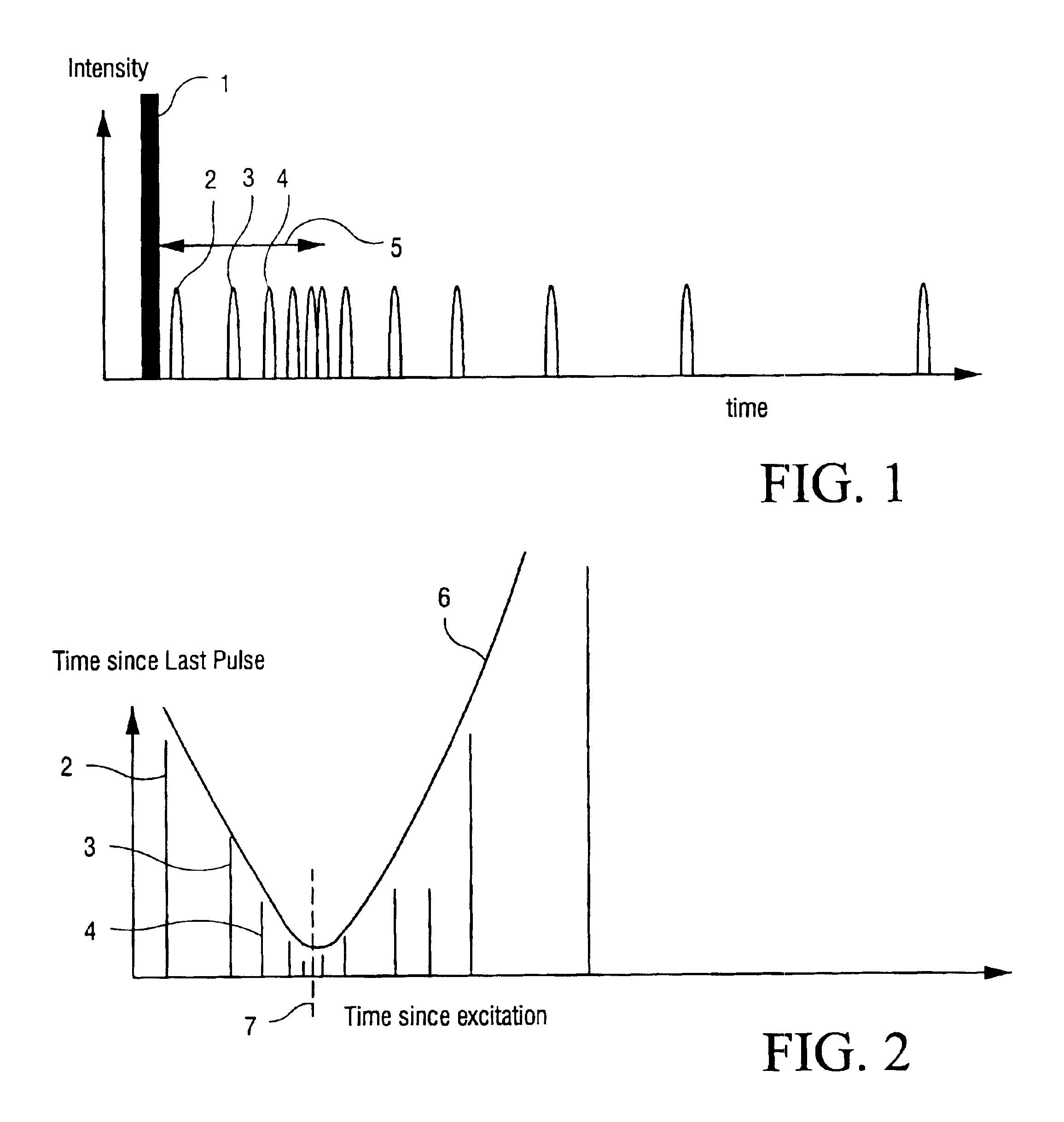
Referring to FIG. 1, this illustrates the excitation of and emissions from a sample which has fluorescent properties having a characteristic lifetime. An excitation pulse 1 is used to excite the sample and as a result a series of photons is emitted, each photon being detected to generate a signal pulse. The first three photons emitted after the excitation pulse 1 are indicated in FIG. 1 by pulses 2, 3 and 4. The arrow 5 in FIG. 1 represents the characteristic lifetime of the excited sample.

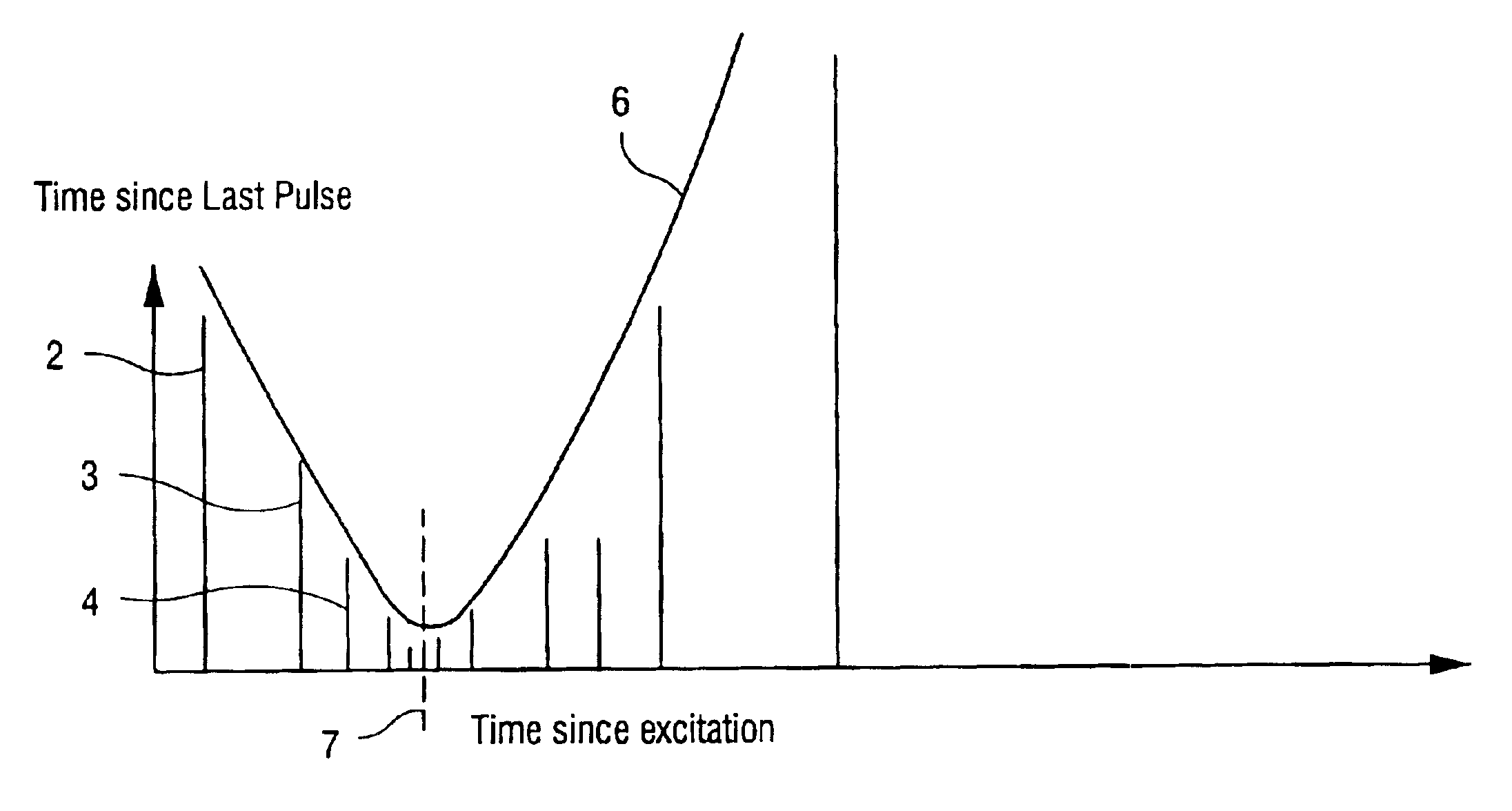
Referring to FIG. 2, this represents data extracted from the events represented in FIG. 1. The horizontal axis corresponds to the time interval which has elapsed since excitation when an emission pulse is detected. The lines corresponding to the signal pulses 2, 3 and 4 in FIG. 1 are identified by the same numbers in FIG. 2. The vertical axis corresponds to the time interval which has elapsed since the preceding signal pulse in the series. Thus the length of the line 3 in FIG. 2 corresponds to the...


PUM

PropertyMeasurementUnit
decay timeaaaaaaaaaa
timeaaaaaaaaaa
timeaaaaaaaaaa

Abstract

A characteristic response of a medium to an excitation transient of predetermined duration which causes the medium to emit a series of signals over a period of time which is long relative to the duration of the excitation transient is assessed. The signals are detected and the duration of each interval between successive signals is measured. A relationship relating the interval between the excitation transient and the emission of each signal to the interval between each signal and the preceding signal in the series is derived to represent the characteristic response.

Description

1. Field of the InventionThe present invention relates to a method and apparatus for assessing the characteristic response of a medium to an excitation transient which causes the medium to emit a series of signals over a period of time which is long compared to the duration of the excitation transient.The present invention is particularly applicable to the assessment of a fluorescent decay but could be applied to any circumstances in which an excitation triggers a response that has decay or other time dependent characteristics which continue for a substantial period of time after termination of the excitation. The nature of the excitation may be the same as or different from the nature of the emission, for example light trigger and light emission or chemical trigger and light emission, and the excited species need not be excited directly, for example excimer and fluorescence energy transfer where the excited species is not the emitting species.2. Description of Related ArtIn convent...

Claims


Application Information

Patent Timeline
Patent Type & Authority Patents(United States)
IPC IPC(8): G01N21/64
CPCG01N21/6408
Inventor LLOYD, CHRISTOPHER J.
Owner UNIV OF MANCHESTER
Learn More