Plasma reactor electrode

Inactive Publication Date: 2004-11-16
APPLIED MATERIALS INC
View PDF13 Cites 80 Cited by
  • Summary
  • Abstract
  • Description
  • Claims
  • Application Information

AI Technical Summary

Benefits of technology

In view of the foregoing, it is one feature of the invention to provide a plasma reactor electrode str

Problems solved by technology

Such bonding creates a problem with respect to uniformity o

Method used


Image

  • Plasma reactor electrode
  • Plasma reactor electrode
  • Plasma reactor electrode

Examples


Example

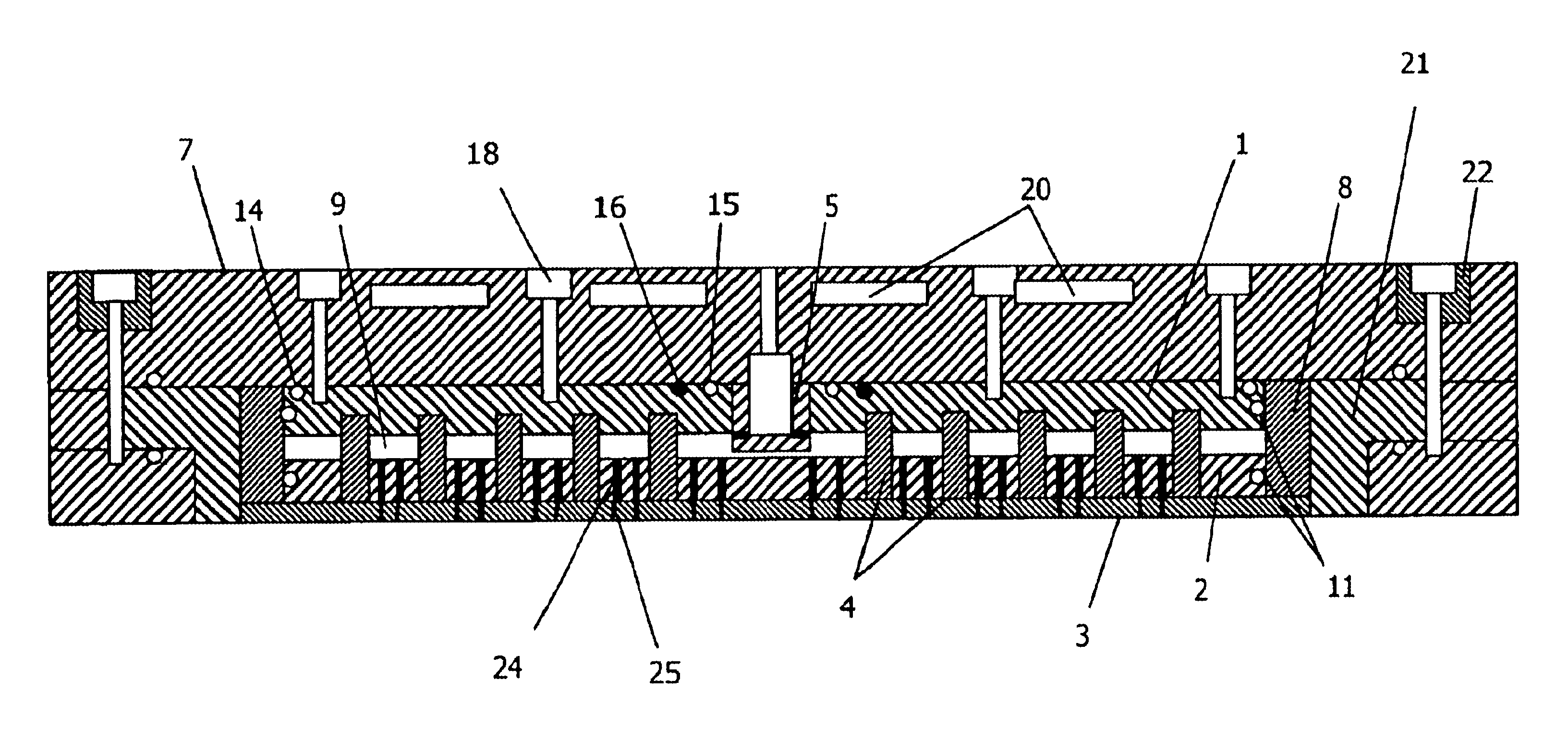
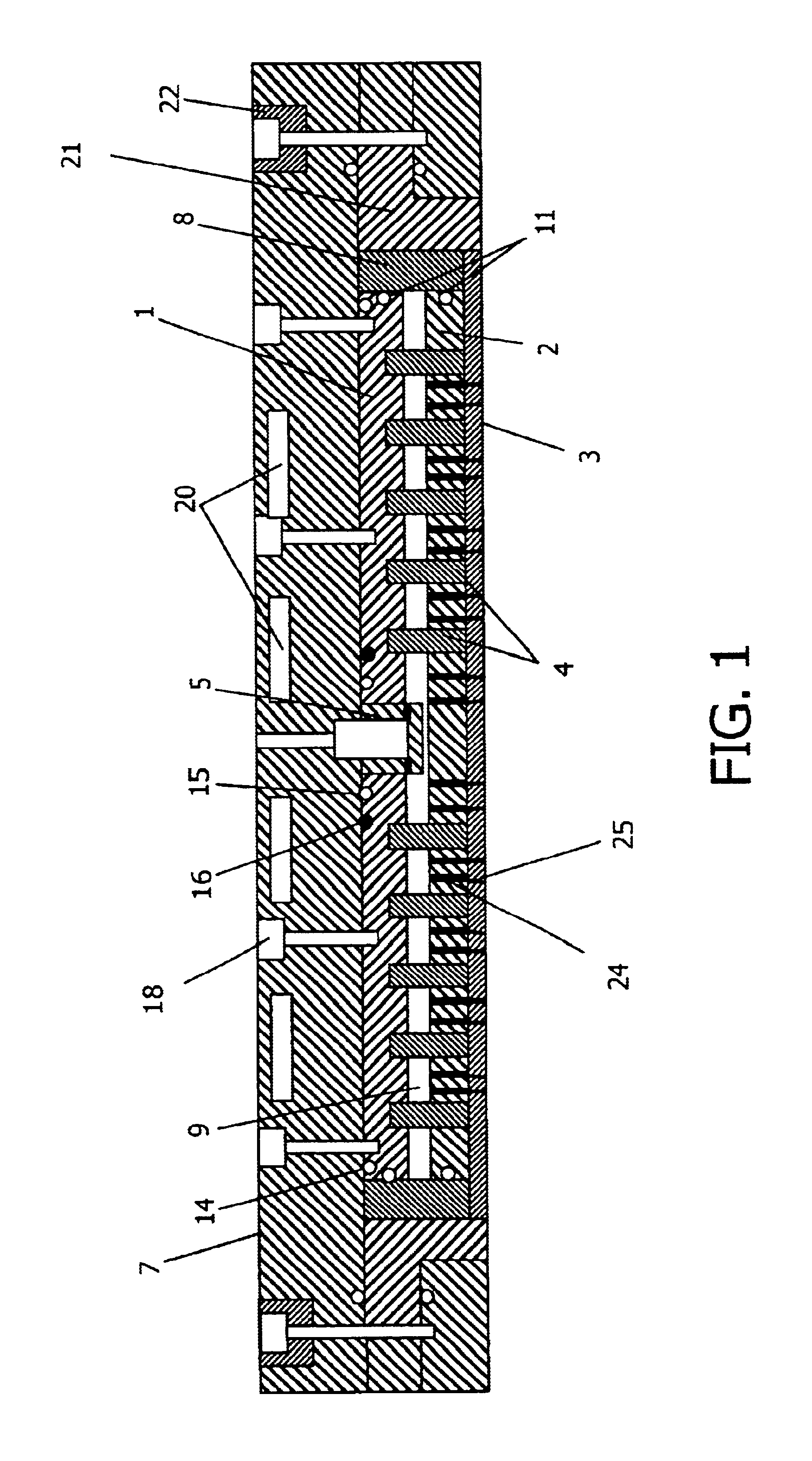
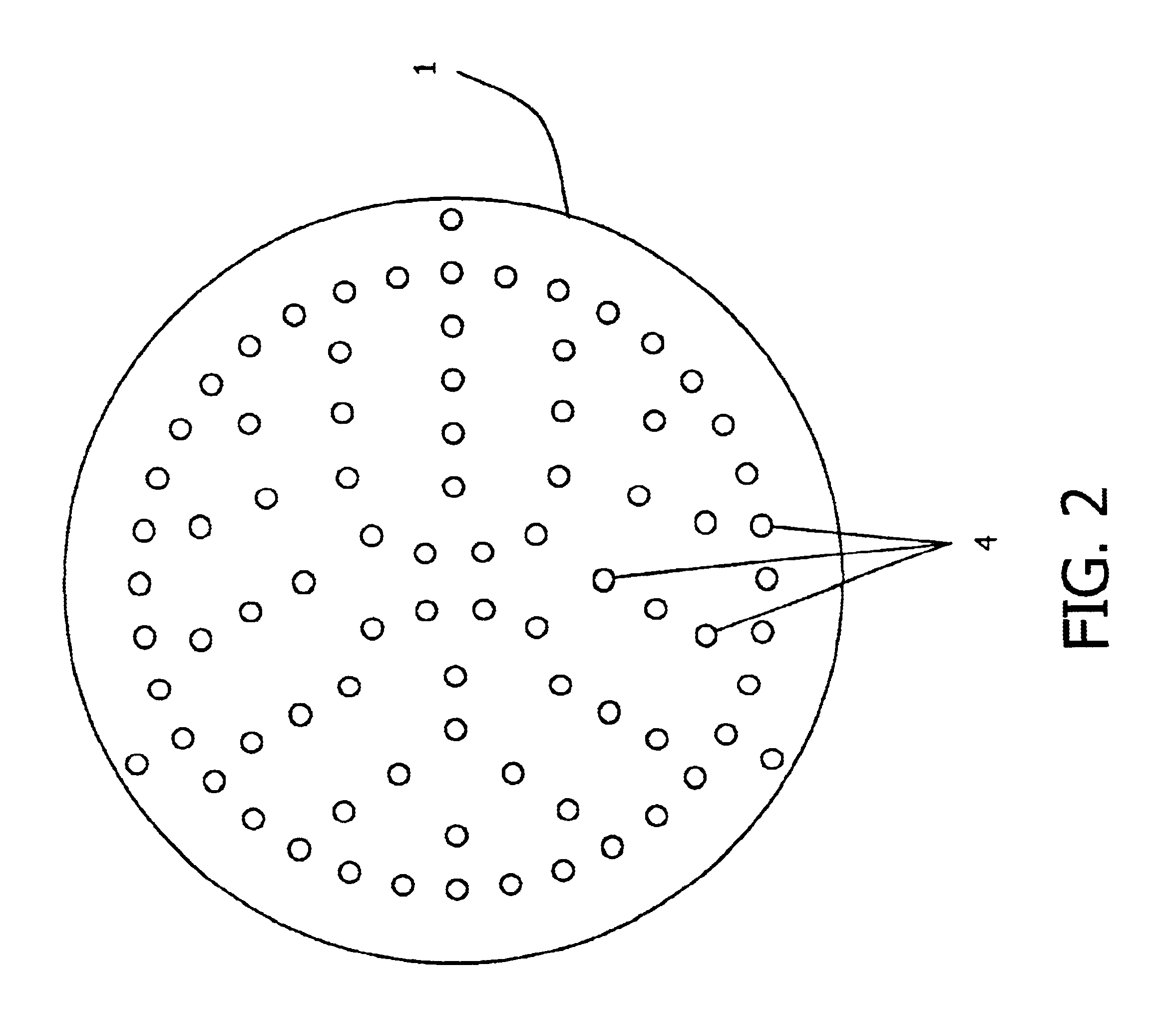
In FIG. 1, an upper plate 1 and lower plate 2 are connected by pins or studs 4. The plates 1 and 2 and the pins or studs 4 are made of electrically conductive material. It also is beneficial for the material to be thermally conductive, but the plates 1, 2 can be made of different materials from that used for the pins or studs 4, and indeed the plates 1, 2 can be made of different respective materials. The composition of the pins or studs 4 also promotes efficient transfer of heat between the lower plate 2 and the upper plate 1 when the electrode is in use, and RF power is applied to it.

The number of pins may be selected, depending on the application, to provide an appropriate balance or mix of heat transfer and power transfer. Consideration as to the number of pins to be selected, and as to placement of those pins, should be based on desired thermal and electrical conductivity characteristics. Such characteristics are well known to those of ordinary skill in this technological field...


PUM

PropertyMeasurementUnit
Dielectric polarization enthalpyaaaaaaaaaa
Thermal conductivityaaaaaaaaaa
Distributionaaaaaaaaaa

Abstract

A plasma reactor electrode, a method of making it, and a plasma reaction chamber employing the inventive electrode, wherein the electrode is configured to provide superior thermal conductivity characteristics. In the inventive electrode, first and second plates are connected by pins. In one embodiment, the pins, and the first and second plates are made of the same material, such as aluminum. The connection of the pins through the first and second plates provides superior thermal conductivity between the first and second plates. A dielectric cover, which may be made of ceramic or quartz, may be added below the lower plate. To form a showerhead assembly, holes are formed in the lower plate, and also in the dielectric cover, in alignment with a plenum chamber, to provide appropriate inlet for process gas into the chamber.

Description

BACKGROUND OF THE INVENTIONThe present invention relates to a plasma reactor electrode, and more particularly to a plasma reactor electrode which provides uniform cooling and consistent delivery of RF power.Various structures of plasma reactor electrodes are known in the art. Two such structures are shown in U.S. Pat. Nos. 5,074,456 and 6,073,577. In U.S. Pat. No. 5,074,456, a silicon electrode is bonded to a support ring via brazing techniques, or through the use of a metal-filled epoxy. In U.S. Pat. No. 6,073,577, the electrode is bonded to a graphite support ring by an elastomeric joint. In both of these techniques, the silicon electrode is bonded only at one of its edges, and thus is bonded only along a limited contact surface. Such bonding creates a problem with respect to uniformity of heat transfer when RF power is delivered to the electrode.It would be desirable to provide a plasma reactor electrode which provides more uniform transfer of heat, and which in addition transfer...

Claims


Application Information

Patent Timeline
IPC IPC(8): H01J37/32
CPCH01J37/32532H01J37/32009
Inventor BARNES, MICHAELPALAGASHVILI, DAVID
Owner APPLIED MATERIALS INC
Why Eureka
Try Eureka